TM9-2330-358-14&P
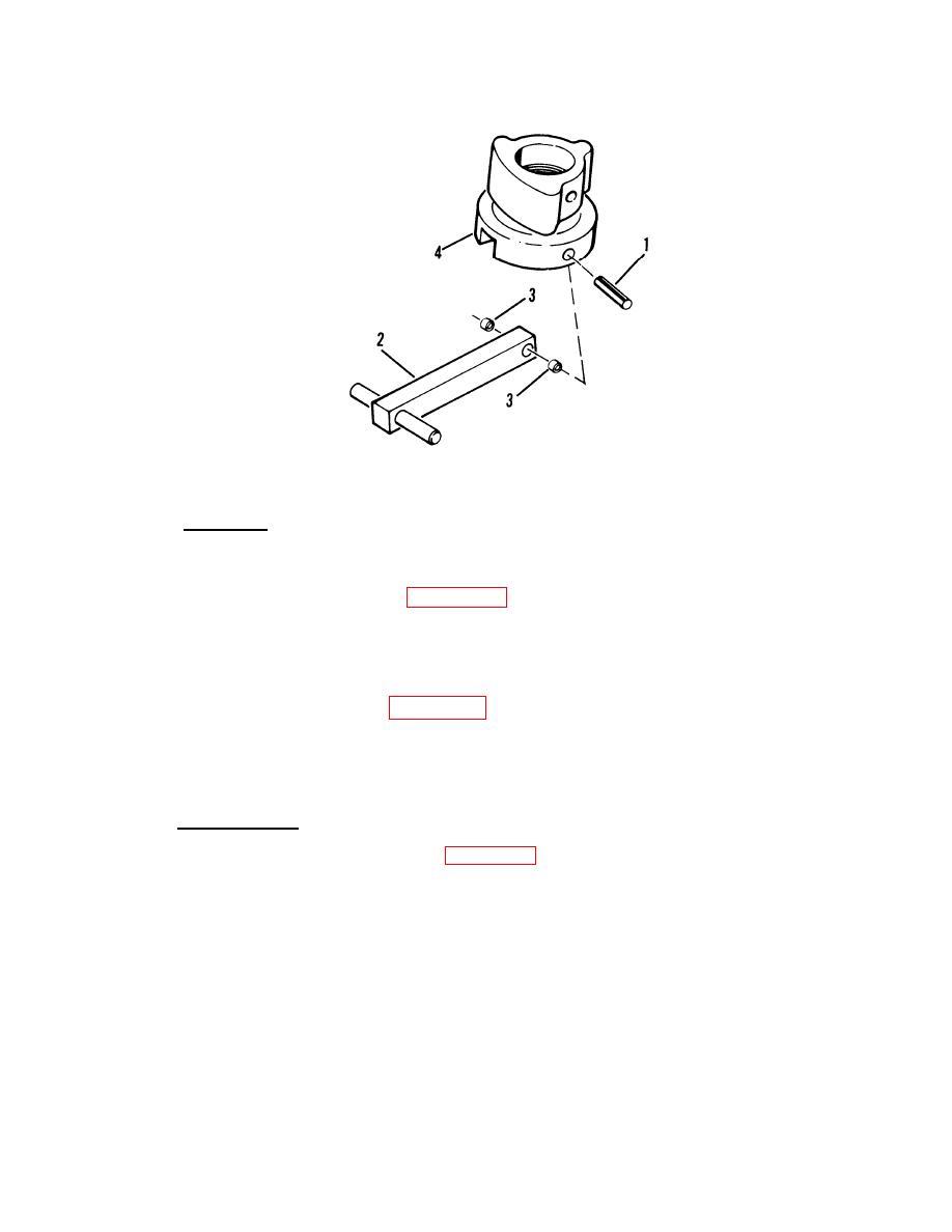
Figure 4-48.
Retractable Twist Lock Lower Assembly
d.
Assembly.
(1) Lower assembly.
(a) Install handle (2, fig. 4-48) and two spacers (3) to base cap (4).
(b) Install pin (l).
(2) Upper assembly.
(a) Place spring (7, fig. 4-47) and ball (6) into position.
(b) Install locator block (4) to bayonet (5).
(c) Install ball (3), spring (2) and setscrew (l).
e.
Installation.
(1) Install upper assembly (3, fig. 4-46).
(2) Install lower assembly (2).
Turn clockwise and align holes for pin (l).
(3) Install pin (l).
TASK ENDS HERE
4-87


