
TM9-2330-374-14&P
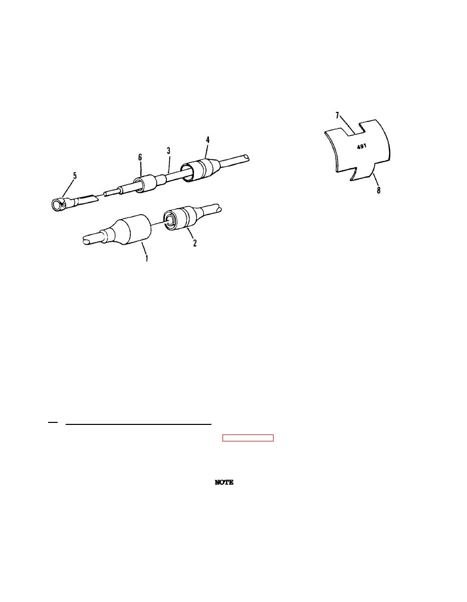
(4) Slide shell (4) and sleeve (6) off wire lead (3). Discard shell (4) and
sleeve (6).
(5) Using wire stripper, strip insulation from wire lead (3) 1/8-inch (3.2 mm)
from end.
F e m a l e connector repair
(6) Slide new shell (4) and sleeve (6) on wire lead (3).
Apply insulation
compound to end of wire lead (3).
( 7 ) S l i d e new terminal (5) on wire lead (3), and using crimping tool, crimp
end.
(8) Slide shell (4) and sleeve (6) down over terminal (5) until seated.
(9) Apply insulation compound to outside of female connector (1).
Push
connectors (1 and 2) together until seated.
( 1 0 ) Connect power.
Turn on semitrailer lights and check for proper operation.
Circuit Marker Band Replacement.
c.
( 1 ) Open tab ends o f marker band (7,
figure 4-17) and remove.
D i s c a r d marker
band (7).
( 2 ) U s i n g e t c h i n g t o o l , etch proper number on new marker band (7).
See
electrical
schematics
(figure 4-18 through 4-21).
(3) P l a c e m a r k e r b a n d ( 7 ) o n w i r e l e a d ( 3 ) .
Using crimping tool, bend tab
ends (8) over wire (3).
4-40
