
TM 9-2330-384-14&P
4-70. JET LEVEL SENSOR REPLACEMENT (Con't).
c.
REMOVAL OF JET LEVEL SENSOR TUBING AND FITTINGS
WARNING
When working inside tank, always provide adequate forced air ventilation
at the manhole opening with air directed into compartment where work
is being performed. Forced air ventilation allows for removal of any ex-
plosive quantities and contaminants resulting from the type of work be-
ing done, and serves to prevent oxygen deficiency. Failure to follow this
warning may result in death to personnel.
NEVER work alone Inside a tank; a second person must be stationed at
the manhole opening. The person inside the tank must have a safety line
and harness on in case of emergency for rescue operations. In the event
a rescue operation is required, summon assistance IMMEDIATELY. DO
NOT attempt a rescue until assistance has arrived.
NOTE
Tag all tubing at jet level sensor (6), emergency valve (12), and strainer
assembly (24) for Installation.
(1) At emergency valve (12) under
semitrailer, remove tubing (23)
from between straight adapter
(22) and outlet of strainer assem-
bly (24). Remove tubing (25)
from between straight adapter
(26) and inlet of strainer assem-
bly.
(2) Remove straight adapters (22
and 26) and bleeder valve (27)
from emergency valve (12).
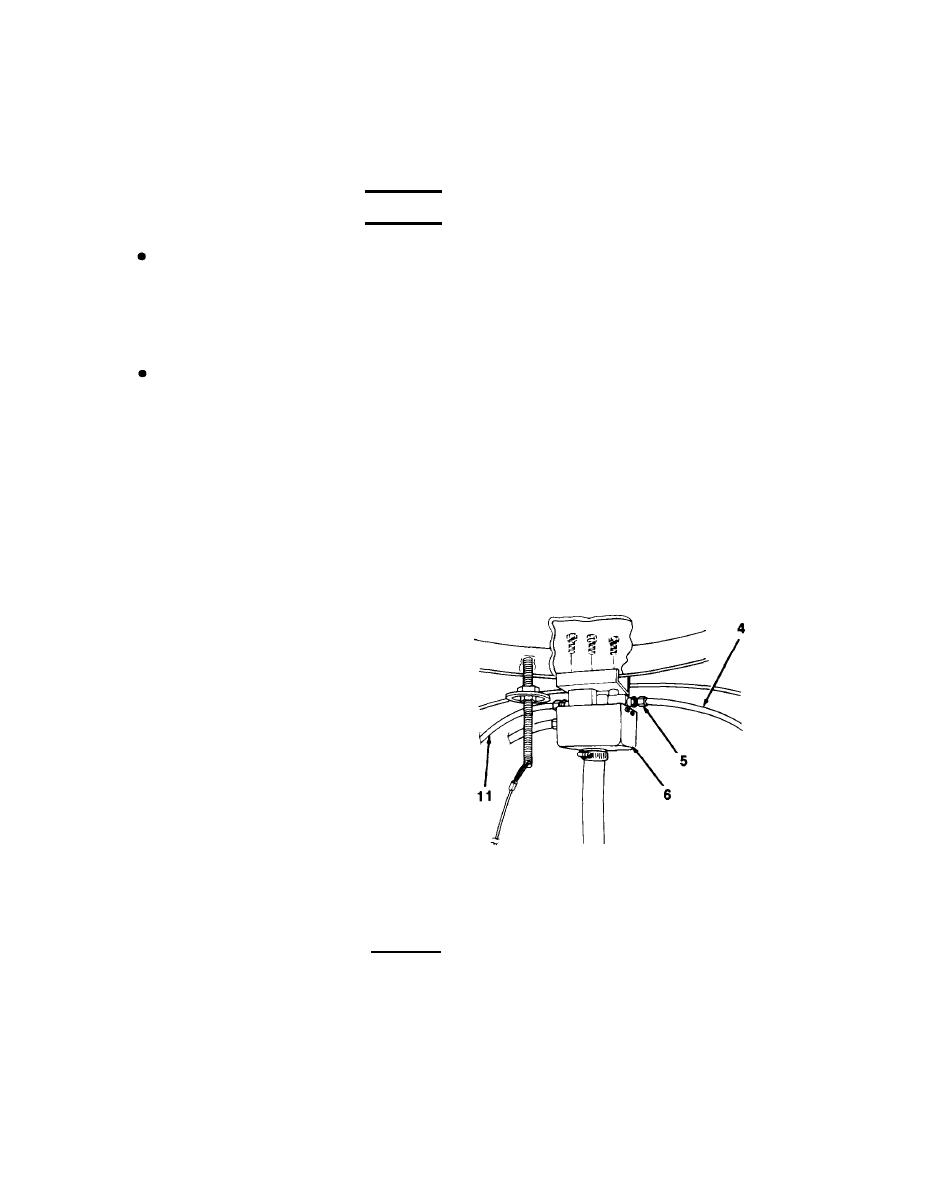
(3) Loosen nuts (5) and disconnect
tubing (4 and 11) from jet level
sensor (6).
(4) Inside tank at emergency valve
(12), loosen nuts at straight
adapters (15 and 19) and discon-
nect tubing (4 and 11).
CAUTION
Use caution when releasing tubing (4 and 11) from under clips (13). Clips
should be lifted gently and only enough to release tubing. Improper han-
dling of clips will cause them to break.
(5)
Remove tubing (4 and 11) from clips (13). Remove tubing from between emergency valve
(12) and jet level sensor (6).
4-218
