
TM9-2330-386-14&P
5-5 AXLES (CONT).
(1) Install two pads (8) with rounded edges on spring (10). Install end
cap (7).
(2) Install two U-bolts (6), four washers (5), and lock nuts (4). Do not
tighten lock nuts.
(3) Install four capscrews (3), washers (2), and lock nuts (1). Do not tighten
lock nuts.
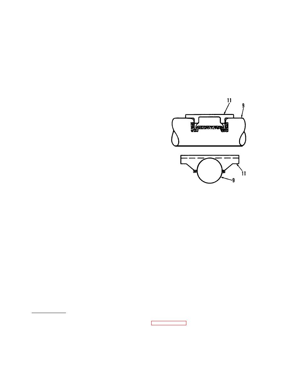
( 4 ) S p r i n g s e a t s ( 1 1 ) m u s t b e arranged so
that the center of the seat is at the
top of the axle (9) beam. The exact top
o f the axle beam is indicated by a 0.31
inch die hole at the top center of the
axle.
(5) Both spring seats (11) must be parallel.
(6) Place axle (9) in position under
s u s p e n s i o n . Be sure spring seats (11)
are equal distance from the axle beam
center hole. Spring seats (11) should
a l s o be the same distance from the brake
spiders.
(7) Spring seats (11) must fit tight to the
WELD POINTS
axle beam.
WARNING
W e a r welding mask, gloves, and apron when welding or
using cutting torch. Failure to wear adequate protective
clothing may result in serious injury.
CAUTION
Do not attach welding ground clamps to U-bolts, springs,
o r axles except at designated weld points. These parts
should be protected from weld spatter.
( 8 ) T a c k w e l d s p r i n g s e a t s ( 1 1 ) i n p l a c e . T h e n recheck to be certain that the
spring sea ts ( 11 ) are still
level, parallel,
properly located and alined.
L o w e r axle (9) .
(9) Weld spring seats (11) to axle (9) using 3/8 inch fillet welds. Welds
s h a l l be per Class 2, MIL-STD-1 261.
d. Axle
Installation
(1) If necessary, install brake camshafts (para. 4-35).
5-4
