TM 9-2330-388-14
1.
Disconnect water pressure hose from back of
4-18.
Indicator Lamp Replacement
gage and plug hose.
1.
Remove two lamp wires at back of lamp. Press
2.
Remove two plastic nuts and washers that
in plastic tabs on side of socket to remove lamp.
secure water pressure gage to panel. Pull gage forward
to remove.
2.
Push new lamp in from front of panel. Connect
two lamp wires.
b.
Installation
4-19.
Panel Lamp Bulb and Lamp Replacement
1.
Insert water pressure gage from front of panel
and secure gage studs with two plastic washers and
a.
Bulb Replacement
nuts.
1.
Pull shield from lamp and replace bulb.
2.
Free hose of plug and install at back of water
b.
Lamp Replacement
pressure gage.
1.
Disconnect wire from panel lamp.
4-22.
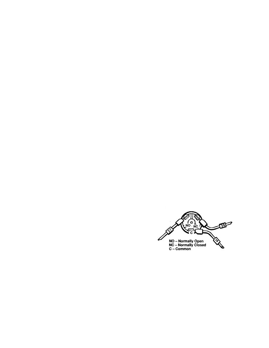
Oil Pressure Switch
2.
Remove nut and washer securing lamp to panel
and remove lamp.
a.
Removal.
3.
Install lamp into front of panel and secure with
1.
Remove three screws and wires at bottom of
washer and nut.
switch.
4-20.
Panel
Ignition
Switch
Removal
and
2.
Remove switch.
Installation.
b.
Installation
a.
Removal
1.
Remove four screws, flat washers and lock
1.
Install replacement switch so that the number of
washer, and sheet metal nuts that secure panel cover to
turns for installation is counted. Remove switch.
base.
2.
Feed shrink tape on all three wires.
Position
2.
Remove three wires from panel ignition switch,
shrink tape up wires temporarily.
marking position of wires.
3.
Install wires at switch with screw at each correct
3.
Remove screw and lock washer that hold switch
location, Fig. 4-19.
selector to shaft and remove selector lever.
4.
Remove nut and retaining washer securing
switch to panel and remove switch from back of panel.
b.
Installation
1.
Install switch base from back of panel and
secure with nut and retaining washer.
2.
Install selector lever on shaft and retain with lock
washer and screw.
Figure 4-20. Oil Pressure Switch Connections.
3.
Install three ignition wires to switch.
4.
Rotate switch in same direction as you removed
4.
Install four screws, flat washers, lock washers
it in step 1 with the same number of turns. Insert the
and sheet metal nuts that secure panel cover to base.
switch into the housing and installed it. Blly doing
operation in this manner, wires should not be twisted
4-21.
Water Pressure Gage
upon installation.
a.
Removal
5. Use heat gun to heat shrink tape on wires.
4-83

