

Custom Search
|
|

|
||
 TM 9-2330-394-13&P
ELECTRICAL SYSTEM TROUBLESHOOTING - Continued
0036 00
ELECTRICAL SYSTEM - Continued
Table 1. Electrical System Troubleshooting Procedures - Continued
MALFUNCTION
TEST OR INSPECTION
CORRECTIVE ACTION
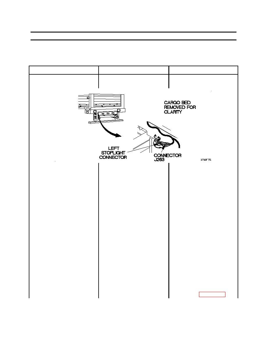
11. LEFT STOPLIGHT DOES NOT
2.
Check to see if 8-14 vdc is
1.
Disconnect connector J263
ILLUMINATE - CONTINUED
present at connector J263.
from left stoplight connector.
2.
Set digital multimeter to
ohms.
3.
Connect positive (+) probe
of digital multimeter to
connector J263.
4.
Connect negative (-) probe
of digital multimeter to a
known good ground.
5.
Position towing vehicle main
light switch to SER DRIVE.
and note reading on digital
multimeter.
6.
Depress brake pedal and
note reading on digital
multimeter.
7.
Release brake pedal.
8.
Position towing vehicle main
light switch to OFF.
9.
If 8-14 vdc is present,
replace composite taillight
assembly (WP 0049 00).
0036 00-73
|
||
|
||


