
TM 9-2590-209-14&P
b. Disconnect tube from manifold, and remove
d. Install gage and plug to cover assembly (view
tube.
B).
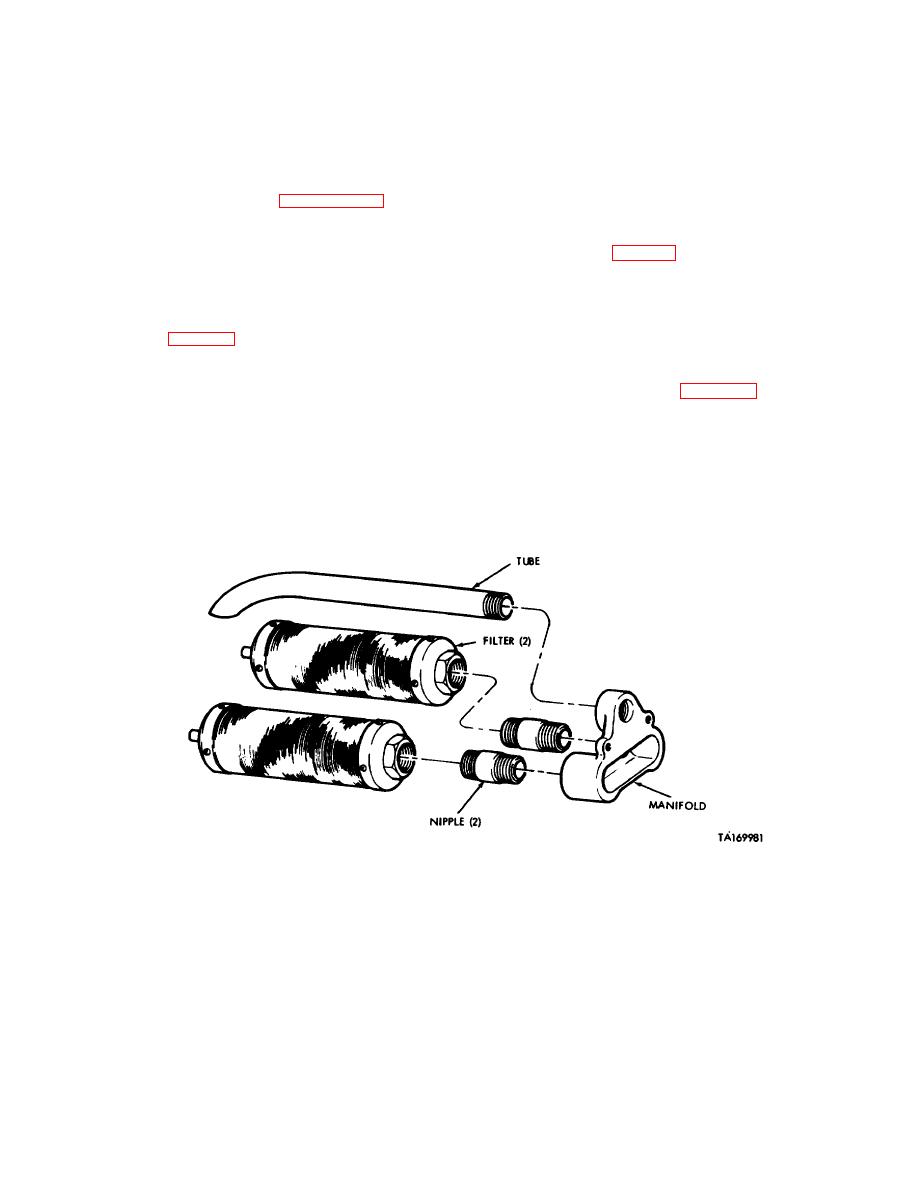
c. Disconnect two nipples from manifold, and
e. Install gasket and cover assembly on reservoir,
remove nipples.
and secure with 14 screws and lockwashers (view A).
d. Clean in accordance with paragraph 5-5.
f. Install tube assembly and connect to elbow
(view A).
e. Connect two nipples to manifold.
4-65. Installation (Fig 4-17).
f.
Connect tube to manifold.
a. Attach hoist to reservoir assembly, and install
g. Connect two filters to manifold.
reservoir assembly on left rear fender (view F).
b. Install two washers, lockwashers, and nuts
4-64. Assembly (Fig 4-18).
securing reservoir assembly to left rear fender (view F).
a. Install baffle in reservoir, and secure with three
c.
Install air vent filter (para 4-100).
screws, lockwashers, and washers (view C).
d. Install tube assembly and hose to reservoir
b. Install manifold assembly inside reservoir, and
assembly (view E).
secure with two screws and seals (view C).
e. Install two elbows to hose assemblies (view D).
c. Install strainer element to cover assembly, and
secure with four screws and lockwashers (view B).
Figure 4-19. Repair of reservoir assembly manifold.
4-40
