
(3)
Remove table center plate and post saw guard.
Install a 1-inch wide saw band and apply cor-
rect band tension.
(4)
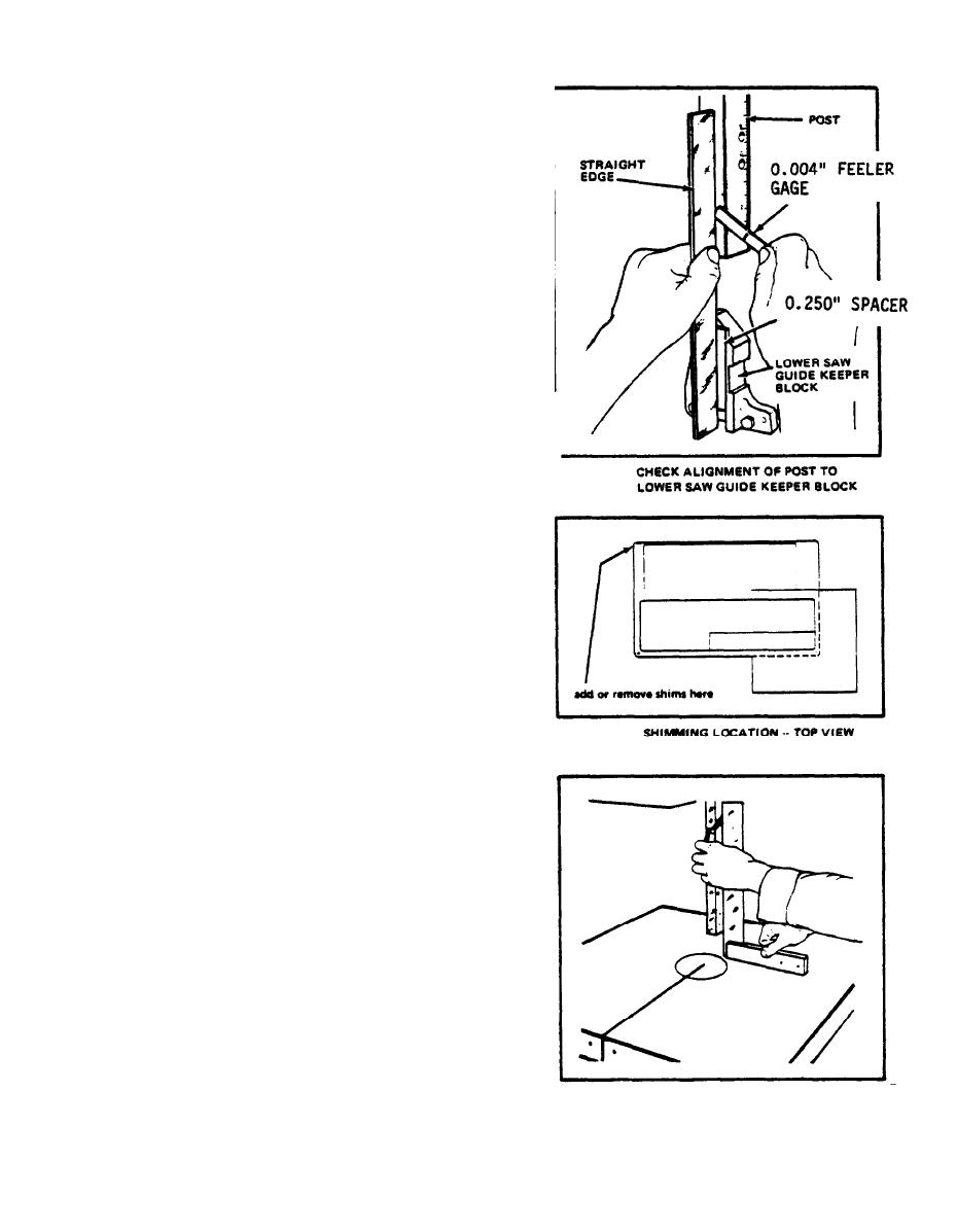
Clamp or hold a straight edge to the front face
of the post and the face of the lower saw guide
keeper block.
(5)
The post should be parallel with the machined
saw guide mounting recess in the lower keeper
block. As shown in the sketch, this parallel-
ism is checked by placing a spacer block
(ground to exactly 0.250" thickness) in the
keeper block. T h e n p l a c e a n a c c u r a t e s t r a i g h t
edge against this spacer block and the post.
Using a feeler gage, check the clearance and
parallelism of the post to the straight edge.
A clearance of 0.004" or less is required.
(6) Adjust the gap by adding shims (to increase
gap) or removing shims (to decrease gap) under
only the mounting bolt location shown in draw-
ing.
(7)
Replace table center plate and post saw guard.
(8)
Loosen table tilt trunnion lock nut with the
wrench furnished with the machine. Square the
table to the post and check as shown above.
Tighten the trunnion lock.
(9)
If necessary, adjust the tilt angle pointer to zero.
(10) The back of the band should be just touching
the saw guide back-up insert. Adjust upper
wheel tilt, if necessary, so that band is posit-
ioned and will track properly. (See Track-
ing the Band in Operation Chapter).
SQUARE TABLE TO POST AND
TIGHTEN TABLE TILT LOCK
3
