TM 9-3405-215-14&P
NAME
NUMBER
1434
PROJECT
ENGINEERING ADJUSTMENT SUMMARY
120789-2
4
11
SHEET
OF
MODEL DBW-15
Welder Jaw Alignment - - continued
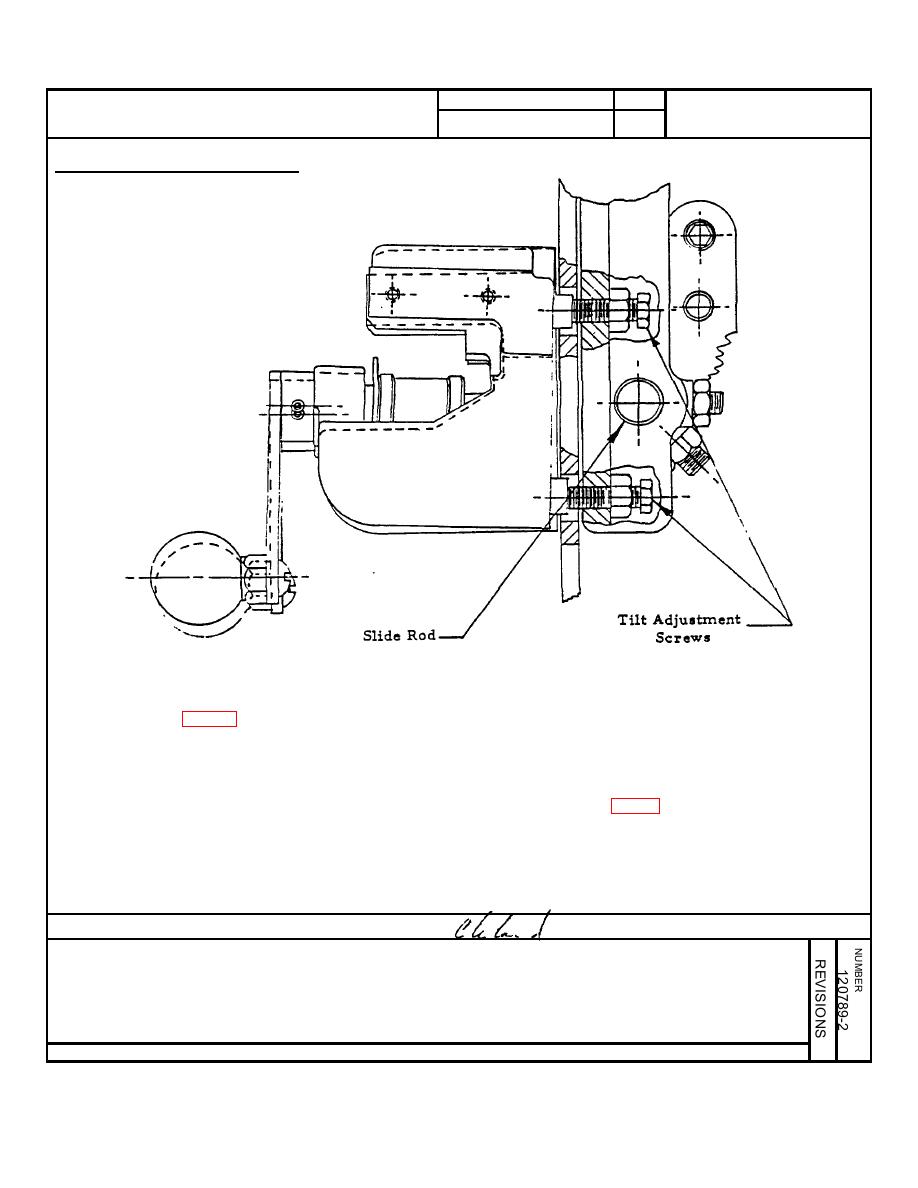
FIG. 3
3. Fig. 3 is an example of twist misalignment. The movable jaw must be
adjusted to correct this problem. Two adjustment screws are provided. Both
of them must be used when making a correction. Care must be taken to
prevent any binding on the slide rod.
4. Verify the proper setting of the slide rod stop screw (Item 2, Fig. 4). It is
adjusted to maintain 1/4 turn clearance between the end of the stop screw
and the milled flat on the slide rod. The movable jaw must move freely with
both tilt adjustments bearing on the jaw.
Prepared by: Roger Harris
Approved:
Date: 7-31-69
146


