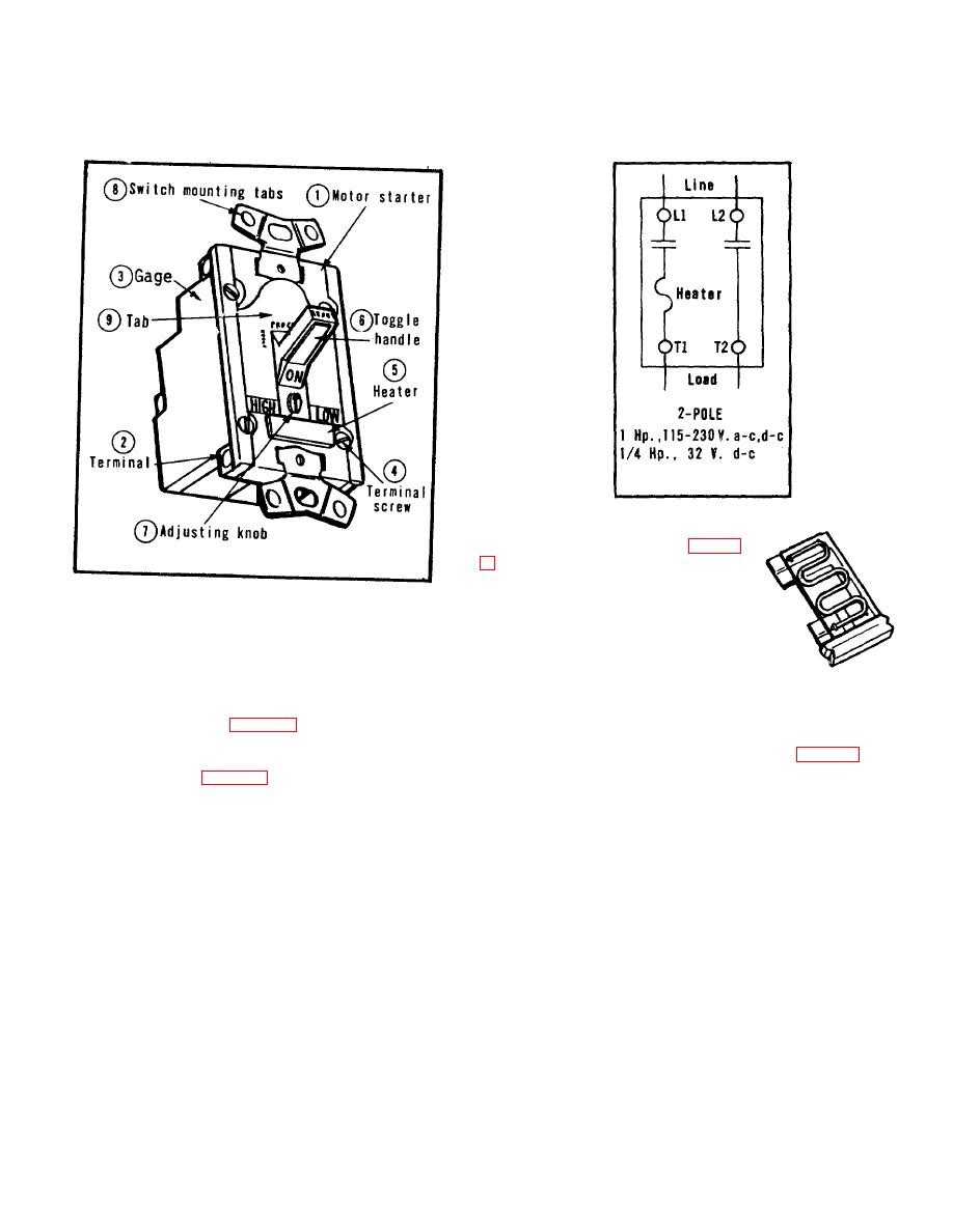
Instructions for Manual Starter
2 Pole Single-Phase, Toggle
Operated.
Figure 2. Wiring Diagram
the adjusting knob (7). (See Figure
hand, no tools required.
Heater
rating is clearly marked on heater for
Figure 1. Manual Starter, Toggle Operated.
easy identification. See Table 1.
Installation, Toggle or Key Operated Manual Starter
1. Select proper enclosure. See Table 2.
Adjustments--Adjustment Knob
2. Strip connecting wires to depth indicated by gage (3)
on side of switch. (See Figure 1) Insert stripped wires
Adjustment knob (7) is located directly below the toggle
straight into terminals (2) and tighten terminal screws (4).
handle (6) on the front of the switch. (See Figure 1.)
See wiring diagrams (Figure 2) or on sides of switch.
Switch is calibrated for i25% of full load motor current
range indicated in Table 1.
3. Mount starter switch to enclosure base tabs with 2
screws furnished.
For closer protection, turn knob clockwise toward low.
Depending on motor characteristics, this setting may be
less than full load motor current. If switch opens, turn
Adjustments--Heater
counterclockwise until satisfactory operation is obtained.
Heater is of the plug-in type which is keyed for proper
If ambient conditions or motor characteristics result in
positioning and requires no screws. Heater (5) is
nuisance tripping, turn toward high until condition is
inserted in rectangular opening in front of switch directly
corrected
below
50


