
TM 9-3441-104-14&P
OPERATION INSTRUCTIONS
The capacity of the Model HB97-18 Hand Brake is 18 gauge mild steel.
Caution - DO NOT use the brake to bend rods. This will cause damage to the nose bar.
DO NOT exceed the capacity of this hand brake.
ALWAYS use material with square-sheared edges. Rolled edges will cause the material to bow.
Short pieces of material should be bent in the center of the brake in order to equalize the stress.
ALWAYS adjust the brake for different gauge thickness.
NEVER use pipe extension to gain additional leverage on clamp handles.
NEVER bend seams unless the gauge adjustment is set to seam thickness. Be careful not to exceed the brake capacity
when attempting to bend a seam.
MAKE CERTAIN that the angle bar (#18) is attached to the apron assembly (#902) when making capacity bends.
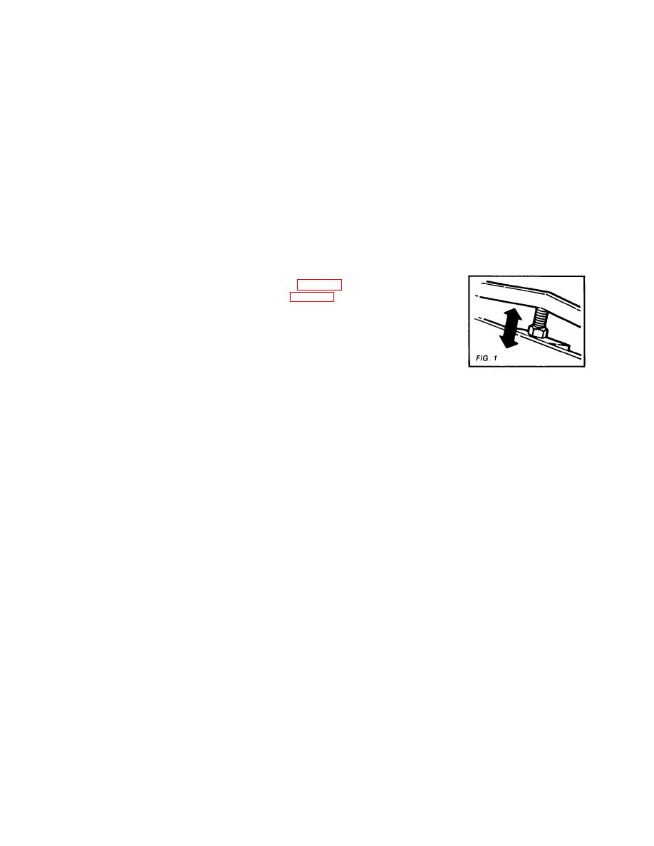
BENDING EDGE ALIGNMENT -- The edge of the leaf (#901) should be flush with the edge of the bottom bar (#902)
brake.)
(A) Adjust bending leaf center with truss nut. (See Figure 1)
(B) Adjust the bottom center with truss nut. (See Figure 1)
(C) With the hinge adjustment screw (#31), adjust the bending leaf ends. Make
sure to loosen hinge bolts (#29) before adjustment and to retighten after
adjustment.
BOWED BENDING LEAF ADJUSTMENT -- Should a bow develop in the center after
use, both tension bolts (#22) should be tightened until center is brought back into a straight line.
ADJUSTING FOR METAL THICKNESS -- Clearance for bends is obtained by moving the top leaf (#901) back at the
bending edge. If material to be bent is within four gauges of the machine capacity, move the top leaf back twice the
thickness of the material by unclamping handles (#7 & #8) and turning the handknobs (#50). When working with lighter
material, move the top leaf proportionately forward if sharper bends are desired. The clamping pressure of the links
(#904) are changed by adjusting the nuts (#12).
COUNTERBALANCE -- To properly counterbalance the bending leaf, raise or lower the counter weight (#35) on the rod
(#34).
DUPLICATE BENDS -- The adjustable stop gauge (#46) may be positioned at any point on the rod (#44) by means of
the lock bolt (#47) to limit the degree of bend.
OVERBENDING ADJUSTMENT -- The top leaf should be set back on the end that the overbending occurs by slightly
unclamping handle (#7 or #8) and turning the handknob (#50). When the correction is made, reclamp the handle.
CREEPING TOP LEAF ADJUSTMENT -- Be certain the brake is level on the floor. (See installing the brake. The top
adjustment screw nut (#53) should be locked into position so that the screws cannot move back and forth. The front
shoulder of the screws (#52) and the face of the collars must be snug against the saddles (#16) with a minimum a- mount
of clearance. If additional creeping exists, place a wedge under the rear of the leg (#907 & #908) at the end that creeps
until the creeping stops. Replace the wedge with a permanent block of the correct height.
CAPACITY -- The bending capacity of the brake is determined by the bending edge thickness provided by the bending leaf
bars (#18 & #20) when mounted on the leaf.
(A) Insert bar (#20) with angle bar (#18) allow the full rated 1" minimum flange on the capacity material.
(B) The insert bar alone, without the angle bar, reduces the capacity of the brake by four gauges.
(C) If both the insert bar and angle bar are removed, the capacity of the brake is reduced by seven (7) gauges. These
bars should be removed only to make narrow offset bends.
LUBRICATION -- Hinges should be lubricated periodically with SAE-30 oil.
The saddle cavities should be greased
periodically to lubricate the top adjustment screws and nuts.
2
