TM 9-4110-258-13
4.27 CONTACTOR (POWER RELAY) K5 TESTING AND REPLACEMENT. - Continued
b.
Removal.
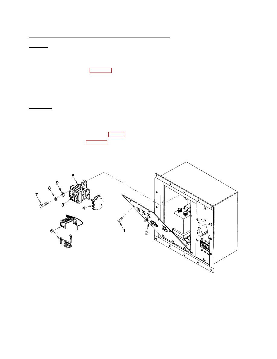
(1) Be sure power has been disconnected at the source and remove six screws (1). Open control box cover
(2).
(2) Remove defrost timer (para 4.29).
(3) Tag and disconnect wire leads (6).
(4) Remove four bolts (7), lock washers (8), flat washers (9), and contactor (5). Discard lock washers.
(5) Remove auxiliary contact (4).
c.
Installation.
(1) Install auxiliary contact (4).
(2) Install contactor (5), four flat washers (9), new lock washers (8), and bolts (7).
(3) Using tags and wiring diagram (fig. 1-4), install wire leads (6). Remove tags.
(4) Install defrost timer (para 4.29).
(5) Close control box cover (2). Install six screws (1).
Figure 4-21. Contactor
NOTE
FOLLOW-ON MAINTENANCE:
Unlatch and close control box cover door.
Connect power and put unit back into service.
4-60

