TM9-4120-370-14
TO35E9-229-1
Section Ill. TECHNICAL PRINCIPLES OF OPERATION
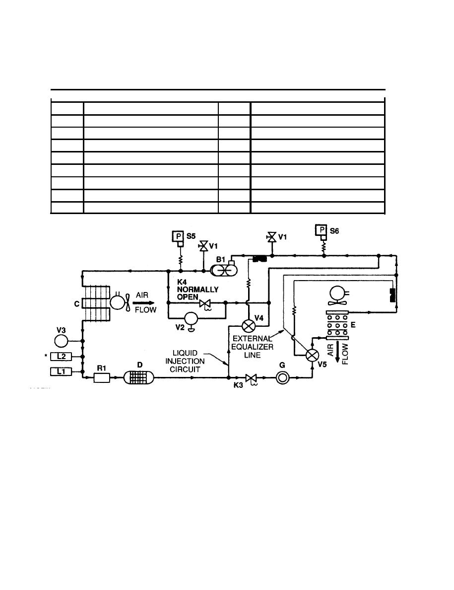
1-11. REFRIGERATION CYCLE
LEGEND
SYM
DESCRIPTION
SYM
DESCRIPTION
B1
COMPRESSOR, RECIP PDVN
R1
TANK, RECEIVER
c
COIL, CONDENSER
S5
SWITCH, HIGH PRESSURE CUTOUT
D
DEHYDRATOR, DESICCANT
S6
SWITCH, LOW PRESSURE CUTOUT
E
COIL, EVAPORATOR
v1
VALVE, ANGLE
G
INDICATOR, SIGHT, LIQUID
V2
VALVE, PRESSURE REGULATING
LI
LINEAR ACTUATING CYLINDER
V3
VALVE, PRESSURE RELIEF
L2*
V4
LINEAR ACTUATING CYLINDER
VALVE, EXPANSION
K3, K4
VALVE, SOLENOID
V5
VALVE, EXPANSION
* NOTE
NORMALLY
THE L2 LINEAR ACTUATING CYLINDER IS USED ONLY OPEN
ON MODELS F36T-2S, F36T4-2S, AND F36T4-2SA
a.
Cooling cycle - Unit operation with mode selector switch set on COOL and the Temperature control thermostat
set to DECREASE.
Compressor (B1) starts.
To prevent compressor overload and damage during startup, solenoid valve (K4) is open at start of cooling
cycle to equalize pressure on both sides of the compressor.
The compressor (B1) takes cold, low pressure refrigerant gas and compresses it to a high temperature,
high pressure gas. This gas flows through the metal tubing to the condenser coil (C) and receiver (R1).
The condenser fans draw outside ambient air over and through the condenser coil (C). The high tempera-
ture, high pressure gas from the compressor (B1 ) is cooled by the flow of air and is changed into a high
pressure liquid.

