
TM9-4120-400-14
CONTROL MODULE WIRING HARNESS.
f. Installation
e. Replacement
d. Repair
c. Testing
b. Removal
a. Inspection
This task covers:
INITIAL SETUP
Equipment Condition
Tools
Remove control module (para 4-21).
Refrigeration Unit Service Tool Kit
Appendix B, item 1
Materials/Parts
Control Module Wiring Harness
Self-locking Screws (3)
Self-locking Nuts (8)
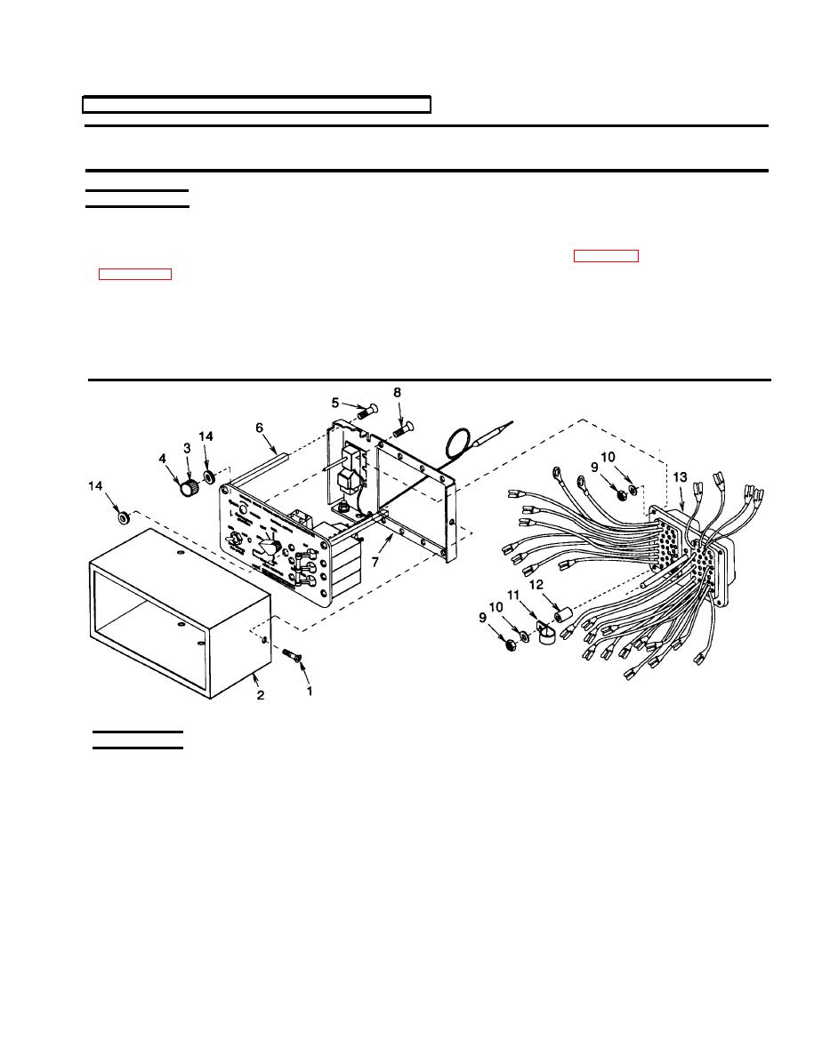
Figure 4-21. Control Module Wiring Harness
INSPECTION
1. Remove four screws (1) and pull the cover (2) off.
2. Inspect connector for loose, damaged or missing pins. Replace if defective.
3. Check individual wires for loose solder connections, loose terminal lugs, cut or frayed insulation, cut or broken
wires.
4-71
