TM9-4120-401-14
LOGIC BOX ASSEMBLY (LGC1). - continued
5-8.
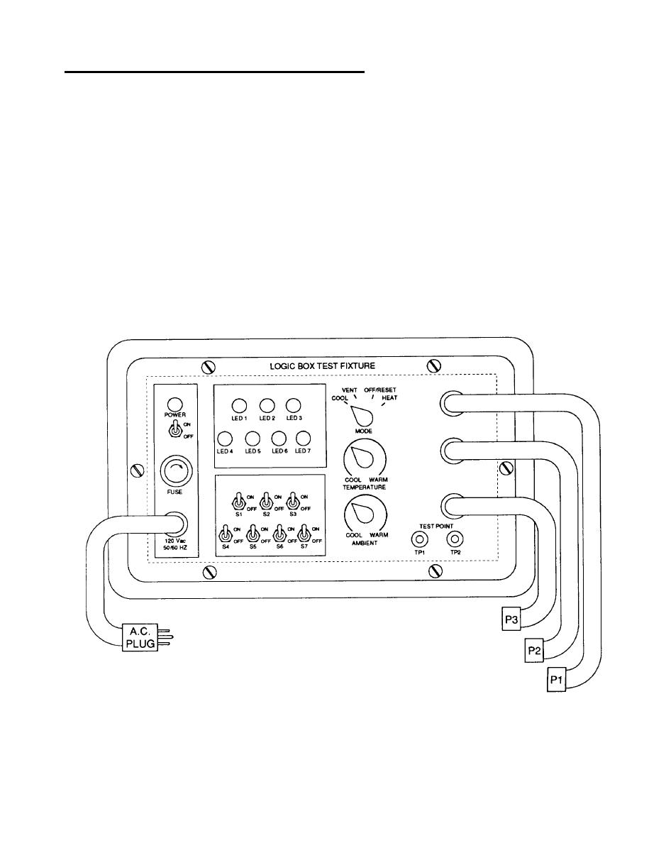
(2) Connect a multimeter set to measure dc voltage to the test fixture TEST POINT (positive lead to TP1
and negative lead to TP2). Connect P1, P2, and P3 to J1, J2, and J3 respectively on the logic box
assembly being tested.
NOTE
If the logic box assembly fails any of the following tests, the entire assembly must
be replaced. Do not continue testing beyond a failure point.
(3) Heat mode test.
(a) Set TEMPERATURE control to WARM position and AMBlENT control to COOL position, MODE
switch to HEAT and switches S1 through S6 to OFF position (contacts closed) and switch S7 to ON
position (contacts open), then turn test fixture power on. After a 2-secmd delay LEDs 1 and 7 shall
illuminate and multimeter shall read 6.3 vdc or higher.

