
TM 9-4120-402-14
4-35. CONTROL ASSEMBLY WIRING HARNESSES. - continued
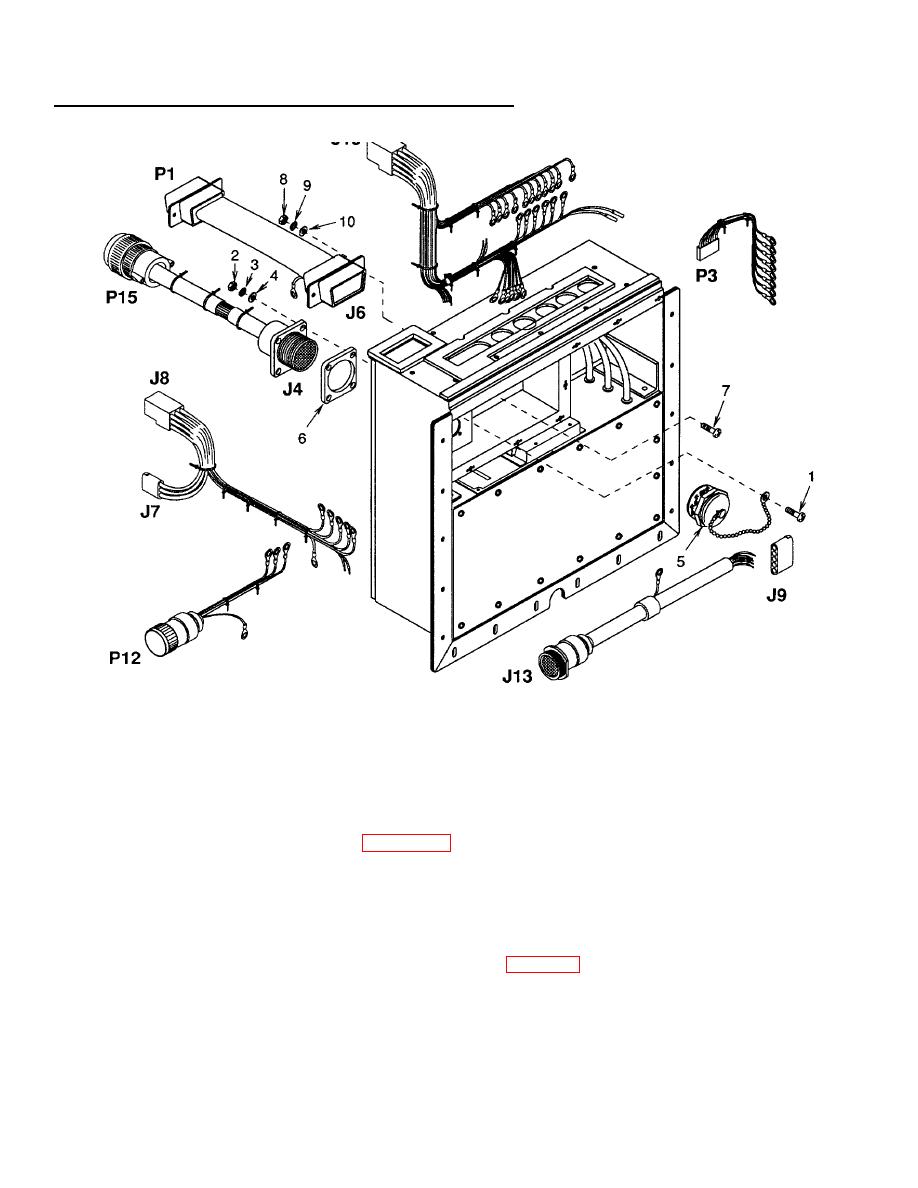
Figure 4-36. Control Assembly Wiring Harnesses
(4) Install connector J6 with two sets of screws (7), nuts (8), lock washers (9), and flat washers (10).
(5) Install connector J4, gasket (6), and cap (5) with four sets of screws (1), nuts (2), lock washers (), and flat
3
washers (4).
(6) Using tags and wiring diagram figure 4-10, connect the wire leads and connectors to unit components.
Remove tags.
NOTE
FOLLOW-ON MAINTENANCE:
Install control assembly (para 4-34).
Connect power at power source.
4-108
