TM 9-4120-407-14
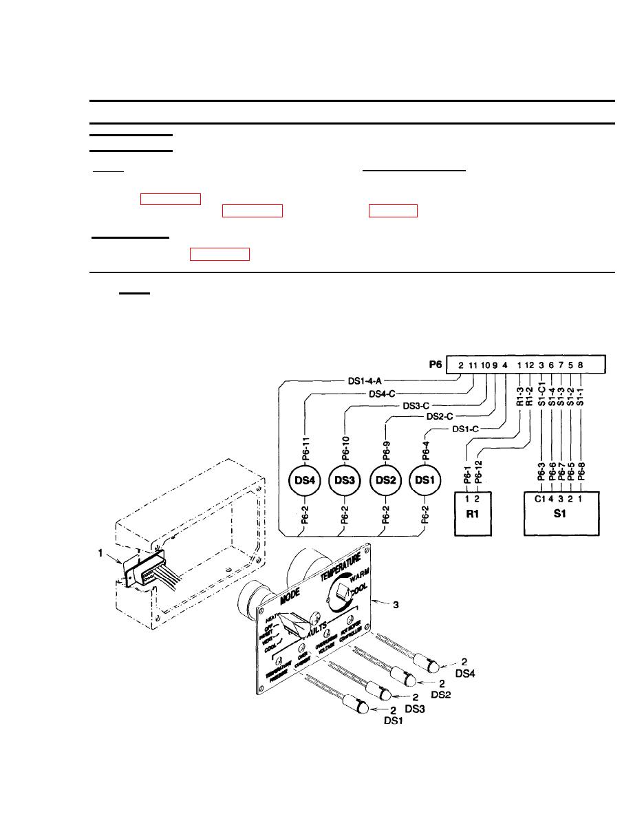
3-23. FAULT INDICATORS (LED'S) TESTING AND REPLACEMENT.
This task covers:
b. Removal
c. Installation
a. Testing
INITIAL SETUP
Equipment Conditions:
Tools
Service Refrigeration Unit Tool Kit
Control panel removed and disassembled as
necessary to access light emitting diodes. See
(Item 1, Appendix B)
Crimping Tool Kit (Item 2, Appendix B)
Materials/Parts
Marker Tag (Item 2, Appendix E)
a. Testing.
(1) Using multimeter set to test diodes, connect red lead to connector (1) pin number 2 and black lead in
turn to pin numbers 4,9,10, and 11 (DS1, DS2, DS3, and DS4). Multimeter should indicate between
1 and 2 volt drop at each pin.
Figure 3-33. Light Emitting Diodes (DS1, DS2, DS3, and DS4)
3-91

