
TM 9-4120-407-14
3-22. POTENTIOMETER TESTING AND REPLACEMENT. (Cont)
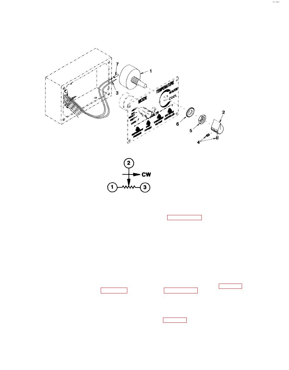
Figure 3-31. Potentiometer (TEMPERATURE Control) (R1)
Figure 3-32. Potentiometer Schematic Diagram
b.
Removal
(1) Tag and disconnect wire leads (3) from potentiometer (1). See paragraph 3-19 for soldering
procedures.
(2) Loosen two setscrews (4) and remove knob (2).
(3) Remove nut (5), lock washer (6), and potentiometer (1).
c. Installation.
(1) Install potentiometer (1), lock washer (6), and nut (5).
(2) Rotate potentiometer (1) shaft to midway position and install knob (2) pointing midscale between
WARM and COOL. Tighten two setscrews (4).
(3) Connect wire leads (3) to potentiometer (1) using tags and control panel wiring diagram Figure 3-5.
Use new sleeving insulation (7) Figure 3-31 as necessary. See paragraph 3-19 for soldering
procedures. Remove tags.
NOTE
FOLLOW-ON MAINTENANCE:
Assemble and install the control panel. See para 3-20.
3-90
