TM 9-4120-408-14
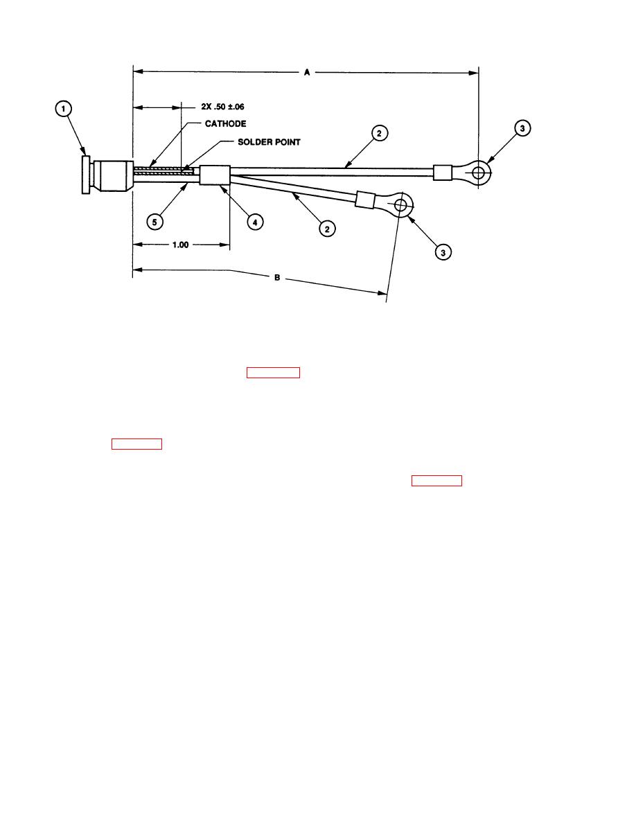
Figure F-5. LED Assembly.
PROCEDURE:
a. Identify faulty lead on LED Assembly (Figure F-5, 1).
b. Remove and discard insulation sleeving (4 and 5).
c. Disconnect faulty lead from cathode or anode.
d. Refer to tables F-8 and F-9 for material and wire lengths to manufacture leads .
NOTE
Ensure assembled LED assembly meets the dimensional requirements of Table F-9 as detailed in
Figure F-5.
e. older terminal (3) to wire (2) and wire (2) to cathode or anode.
f. Install new insulation sleeving (5) over solder joint and shrink to a firm fit.
g. Install new insulation sleeving (4) over both sets of insulation sleeving (5) and shrink to a firm fit.
F-10

