
TM 9-4120-411-14
4.38
LIGHT EMITTING DIODES (FDECU-2 DS1 THRU DS3) (UNITS AFTER FDECU-2 DS2 AND DS3)
REPLACEMENT - CONTINUED.
(4) Assemble remote box (2) halves being sure that no wire leads are pinched.
Secure with four captive
screws (1).
(5) Connect FDECU to power source and operate per paragraph 2.4.
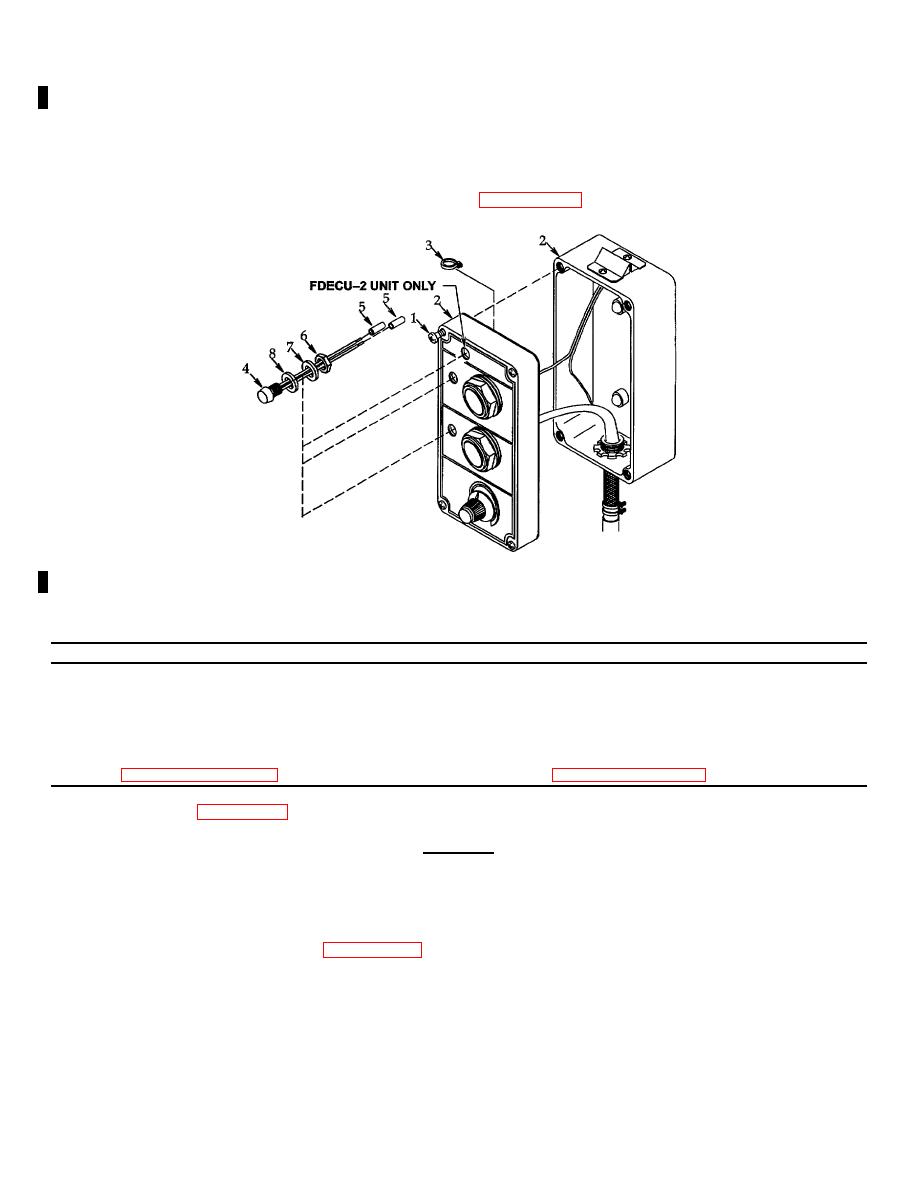
Figure 4-37. Light Emitting Diodes (FDECU-2 DS1 thru DS3) (Units After FDECU-2 DS2 ad DS3).
4.39 PUSH BUTTON SWITCHES (S1 & S2) REPLACEMENT.
THIS TASK COVERS:
a. Removal
b. Installation
INITIAL SETUP:
Tools
Materials/Parts
General Mechanics Tool Kit
Marker Tags (qty 3)
Item 1, Section III, Appendix B
Item 3, Section II, Appendix E
WARNING
Rotating parts and lethal voltage levels are used in operating the FDECU. Be sure
power source is disconnected. Injury or death can occur if connected to power
source.
(1) Shutdown the FDECU per paragraph 2.4 and disconnect it from power source.
(2) Loosen four captive screws (1) then separate remote box (2) halves and lay it open being careful not to
damage wire leads.
(3) Tag wire leads (3). Loosen two screws (4) then remove three terminals (5).
4-94 Change 1
