
TM 9-4120-411-14
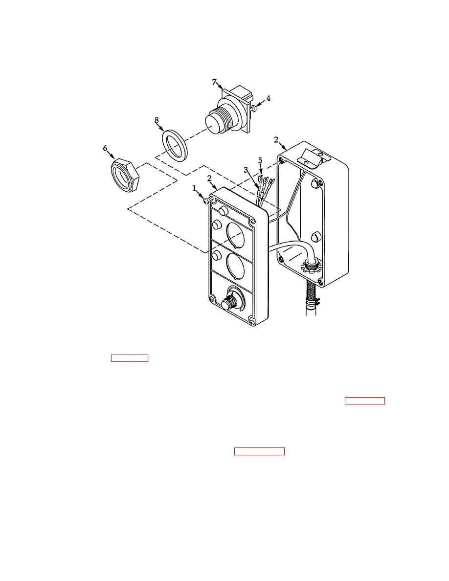
(4) Remove nut (6), push button switch (7), and sealing washer (8).
Figure 4-38. Push Button Switches (S1 & S2).
b. Installation. See figure 4-38.
(1) Be sure sealing washer (8) is on push button switch (7) then install push button switch. Align anti-rotation
key with notch in sealing washer and panel then secure using nut (6).
(2) Loosen two screws (4) then install three terminals (5) using tags and wiring diagram figure 4-14. Secure by
tightening screws. Remove tags.
(3) Assemble remote box (2) halves being sure that no wire leads are pinched.
Secure with four captive
screws (1).
(4) Connect FDECU to power source and operate per paragraph 2.4.
4-95
