
TM 9-4910-387-14-1
1-8.
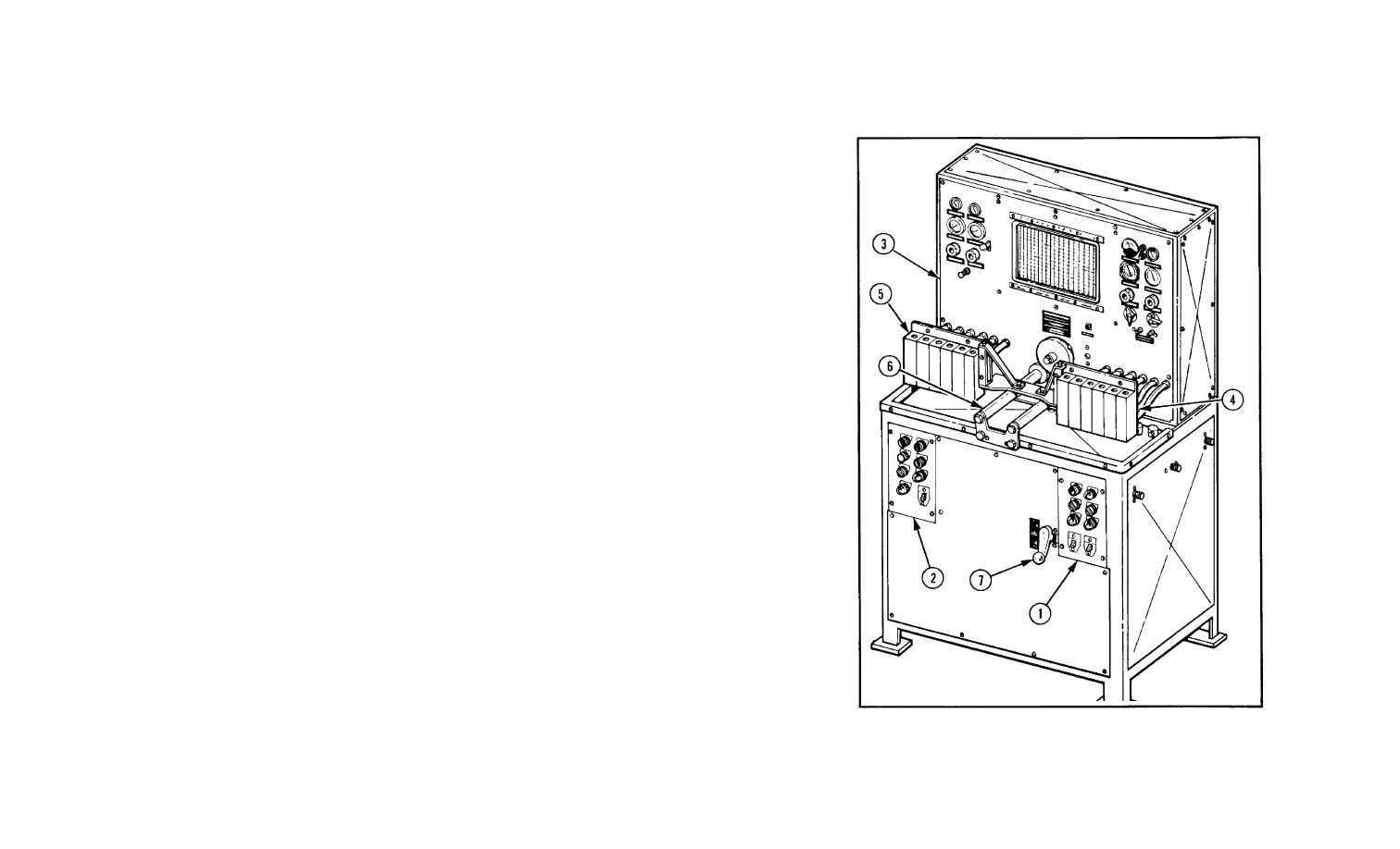
LOCATION AND DESCRIPTION OF MAJOR COMPONENTS
a. Major Components . Refer to the following text and illustrations for location and description
of major components. Side and rear panels must be removed in order to view certain components.
(1) RH AND LH CONTROL EQUIPMENT ASSEMBLIES (1 AND 2). Consists of various
pushbuttons, switches, and indicator lights needed to operate the tester.
(2) INSTRUMENT PANEL ASSEMBLY (3). Consists of pressure and temperature gauges,
TACHOMETER, and various selector valves and regulators; and houses a graduate rack
assembly. Monitors and controls the various functions of a fuel injector pump under test.
(3) RH AND LH ACCUMULATOR ASSEMBLIES (4 AND 5). Accumulates fuel pumped by
fuel injector pump under test and transmits it to burettes in graduate rack assembly.
(4) MOUNTING RAILS (6). Used with an adapter bracket to secure a fuel injector pump to
the tester.
(5) SHIFT CONTROL ROD ASSEMBLY (7).
Shifts the main drive motor from the low
speed range to the high speed range.
1-7
