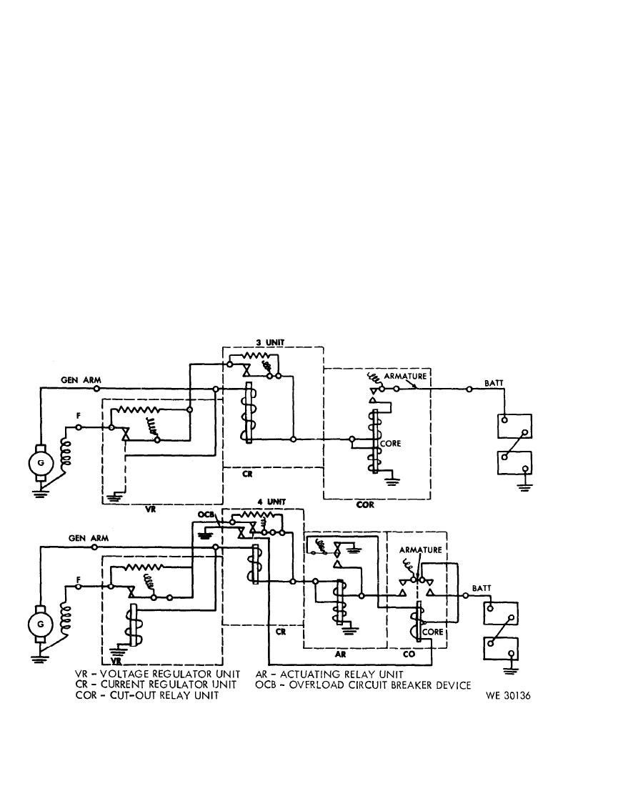
(5) Current regulator unit.
(d) If the ampere reading is not as spec-
(a) P l a c e both the battery switch (20)
ified in (c) a b o v e , a d j u s t m e n t o f
and the starter test load disconnect
t h e current regulator unit will be
s w i t c h (10) in the "ON" position.
required. Stop the varidrive assem-
(b) Start the varidrive assembly as pre-
b l y and place the starter test load
scribed in c(7) above and turn the
disconnect switch (10) in the
s p e e d control handle (22) slowly
"OFF" position. Refer to manufac-
clockwise until 3,000 rpm are indi-
t u r e r ' s literature or pertinent pub-
c a t e d on the tachometer indicator
l i c a t i o n ( s ) covering the generator
meter (3).
regulator for adjustment proce-
d u r e s . After adjustments are made
(c) Place a load of approximately 25-30
continue with tests in (6) below.
amperes in the circuit by placing the
2 5 - 1 2 . 5 fixed load switch (12-C)
(6) Final test procedure for control units.
and the 0-25 0-12.5 load switch
(12-D) in the "ON" position and
regulator but do not secure and start
t h e n turn the variable load 0-25
the varidrive assembly as prescribed
0-12.5 ampere rheostat (13) clock-
in c(7) above. W i t h the control
w i s e about a turn. The ampere
units set as indicated in (e) a b o v e ,
reading on the load dc ammeter (1)
make the following settings of the
s h o u l d be approximately 25 am-
c o n t r o l s and switches on the test
peres.
stand:
contact type generator regulator.

