
pere reading on the load dc ammeter
(4) Start the varidrive assembly by sliding
(1) is approximately 100 amperes and
t h e safety clip (25-B) off the stop
the voltage reading on the dc voltmeter
button (25-C) and depress the start
(4) is approximately 28 volts. The ac
button (25-A) (do not depress the
a m m e t e r (5) should read 72 amperes
start button more than 10 seconds).
and the ac voltmeter (6) should read
Note. Let the test stand operate for about
1 5 minutes or more (depending on ambient
a p p r o x i m a t e l y 25 volts. The reading
temperature conditions) to warm-up the
o n the field dc ammeter (2) will be
generator (alternator) and rectifier before
"0."
p r o c e e d i n g with tests in (6) below.
Note. The load switch (17-D) must be
(5) Turn the speed control handle (22)
in the "ON" position to connect the rheostat
slowly clockwise until 2,000 rpm are
( 1 9 ) , also, adjust the rheostat (19) and the
indicated on the tachometer indicator
dc variable power supply control (26), slowly
meter (3).
until the 100-ampere load is reached and the
r e a d i n g on the dc ammeter (1) is 100 am-
(6) P l a c e the 50-25 fixed local switch
peres. C h e c k the load dc ammeter (1) dur-
(17-B) to the "ON" position and add
ing this procedure and do not allow the
the 25-12.5 fixed load switch (17-C)
ampere reading to exceed more than 100
a n d 0-25 0-12.5 load switch (17-D).
amperes.
T u r n the variable load 0-25 0-12.5
Caution: Never allow the voltage
a m p e r e rheostat (19) clockwise as
r e a d i n g on the dc voltmeter (4) to
n e c e s s a r y to bring the load up to a
exceed 32 volts when performing the
100-ampere load.
operation, (6) and (7) above, or the
(7) T u r n the dc variable power supply
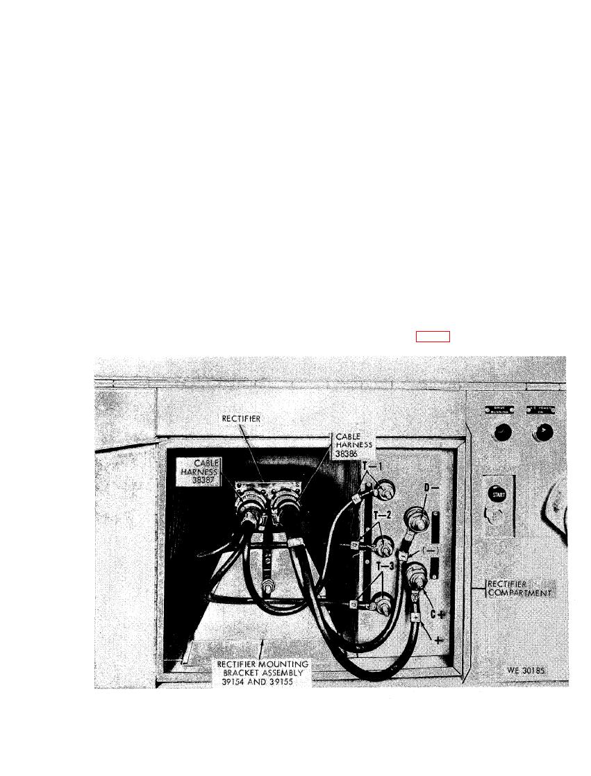
rectifier (fig. 49) may be damaged.
control (26) clockwise until the am-
Leece-Neville Company no. C0011029CP ordnance no. 7954343 100-ampere
rectifier - installed view and hook-up to test stand.
105
