(8) Rotate the ac ammeter phase selector
(10) T u r n the speed control handle (24)
switch (11) through the "PH1,"
p a r t i a l l y counterclockwise until the
v a r i d r i v e assembly speed is reduced
"PH2,'' and "PH3'' positions. The am-
p e r e reading on the ac ammeter (5)
-speed. Place the switches and con-
should not differ by more than 10 am-
trols in table 7 above, in positions in-
peres for all three positions on the ac
of the table.
dicated in column
ammeter phase selector switch.
S t o p the varidrive assembly by de-
pressing the stop button (25-C) on the
(9) Rotate the ac voltmeter phase selector
drive control (25).
switch (14) through the "T1-T2,"
"T1-T3," and "T2-T3" positions. The
(11) R e m o v e the cable harnesses and test
v o l t a g e reading on the ac voltmeter
leads (fig. 48) and continue with test
in e below.
( 6 ) should not differ by more than
plus or minus 1 volt for all three po-
e. Overspeed Test Procedures.
sitions on the ac voltmeter phase selec-
(1) Remove the generator (alternator)
tor switch.
from the low speed driving head (5,
N o t e . If test results are not obtained as
indicated in paragraphs (2) through (9)
driving head (4, fig. 7). Recalibration
above, check the indicator knob on all rotary
o f the tachometer indicator circuitry
switches under the meters (fig. 47) to be sure
the knob is secure on the shaft of the switch
will not be necessary if the generator
a n d pointing to the correct position on the
(alternator) is direct-driven, however,
s w i t c h dial. If this condition exists, place
t h e reading will be taken from the
the knob and switch shaft in the correct
u p p e r scale on the tachometer meter
p o s i t i o n on the switch dial and tighten the
(3.) for the test in paragraph (2) be-
set screw in the knob securely.
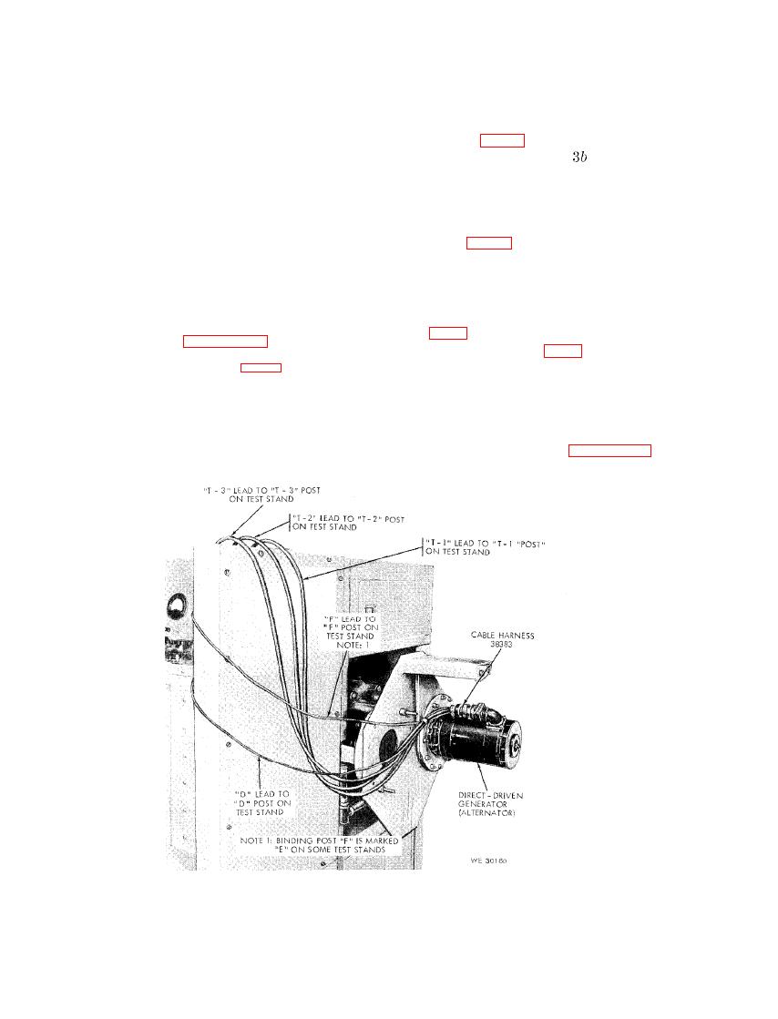
Figure 50. Leece-Neville Company no. A0015504AA ordnance no. 10922191 100-ampere
direct-driven generator (alternator - installed view and hook-up to test stand.

