
that the amount of advance at that speed
b. Reduce tester speed to 200 rpm.
is the same as it was in step b, and as
c. If testing LOADOMATIC type of distrib-
specified. Any inconsistency in readings
utor, turn to the single or dual loadomat-
requires correction for best engine per-
ic distributors paragraphs for remaining
formance.
tests.
(1) If advance is excessive on both steps b
and c, the governor weight springs are
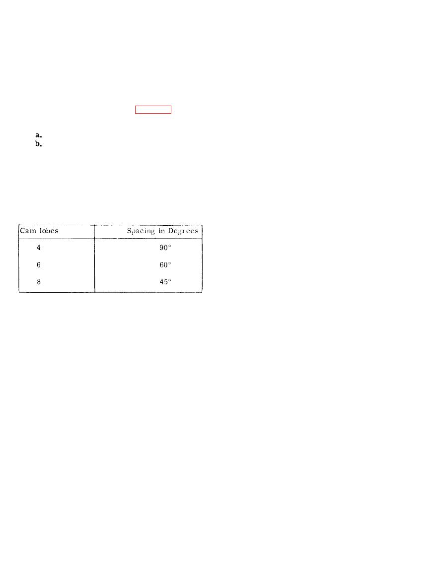
CAM LOBE ACCURACY. (See Figure 6)
weak, or the wrong springs are in-
stalled.
Determine the cam lobe accuracy as follows:
(2) If advance is slow in step b, and ex-
A d j u s t distributor speed to 1000 rpm.
Rotate the degree indicator ring on the
cessive in step c the governor weights
are sticking and should be freed-up.
panel until the zero on the degree ring is
(3) If advance is insufficient both on accel-
aligned with one of the arrow flashes.
eration and deceleration, the governor
c. O b s e r v e relative position of all arrow
spring tension is excessive.
flashes.
T h e arrow flashes should be
(4) Refer to the
specifications for
e v e n l y spaced around the degree ring,
p r o p e r service procedure.
within 1 degree.
d. The spacing in degrees depends on the
number of lobes on the cam.
VACUUM CHAMBER DIAPHRAGM TEST.
The following procedure is for the usual type
of distributor. For LOADOMATIC type distrib-
u t o r s see loadomatic distributors paragraphs.
a. Insert proper adapter in the vacuum ad-
vance unit and tighten with wrench to in-
sure a good seal.
b. Attach hose to adapter and pinch hose with
metal clamp.
c. Adjust vacuum control until the vacuum
MECHANICAL ADVANCE TEST.
gage reads 15 inches.
d. R e l e a s e hose clamp and observe gage.
This test is made to determine if the ignition
Gage reading will momentarily fall to a
timing conforms to the manufacturer's spec-
lower reading.
ified advance curve throughout all speeds of en -
(1) If gage reading returns to 15 inches
gine operation. A defective mechanical advance
within a few seconds the vacuum chamb-
unit will result in the engine being out of time
at certain speeds. This will always result in
e r is air tight.
(2) If gage reading fails to return to 15
loss of performance of the engine, and may also
inches the vacuum chamber is leaky.
cause spark knock and overheating. Figure
6A shows direction of advance f or shaft counter -
VACUUM CONTROLLED BREAKER PLATE
clockwise rotation; 6B for clockwise rotation.
TEST.
The procedure for the mechanical advance test
The breaker plate movement must be smooth and
is as follows:
even as it rotates or the breaker plate will twist,
a. Set zero of the degree indicator ring in
thereby changing the relationship between the
line with the arrow flash nearest the op-
cam and rubbing-block and causing the dwell
erator.
b. Increase distributor speed, pausing at each
angle to change. Any change in dwell angle af-
fects the ignition spark, both in quality and
specified speed to note if the amount of ad-
timing.
vance occuring is within 1 of the spec-
ified figure. (The manufacturer may allow
a. Adjust speed control to 1000 rpm.
more tolerance).
b. Using the vacuum control knob, adjust the
c. Momentarily exceed the highest specified
vacuum reading to zero. Then increase
s p e e d given as a check speed. Then,
vacuum to 20 inches while watching the
while returning the distributor speed to
dwell meter pointer for variations.
zero, re-check at each test speed to see
