
TM 9-4910-707-14&P
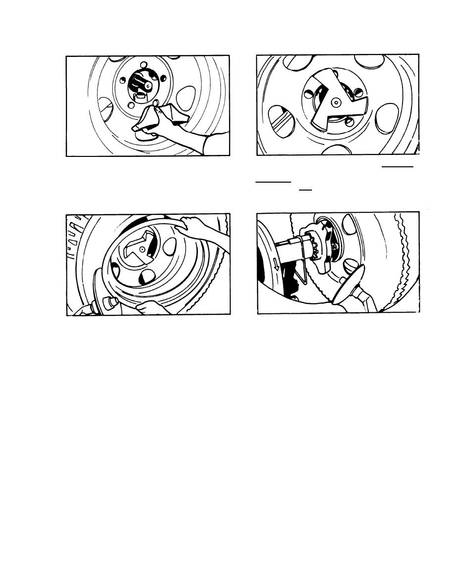
7. RH 5 SPLlT WHEEL ASSEMBLY (DEMOUNTING)*
B. Place the arms
on the special cone a l o n g s i d e of
A. Remove the chuck rods and nut (part #3020) from
the bosses on the
chuck casting and tighten the chuck.
the machine. Position the shaft through the center
C A U T I O N : When
tightening the chuck, be very sure
hole of the wheel and spin on the special reverse disc
Ibs. as indicated on pressure gage.
not to exceed 3 0 0
cone (part #3710), with the tapered side toward the
chuck.
D. Move the press wheel assembly to the other side
C. Break the bead on the side opposite the chuck and
of the carriage and push the tire off of the remaining
remove the outer half, using a tire iron.
portion of the wheel.
*NOTE: This unit can also be serviced by using the
standard chuck rods: Chuck wheel in normal manner,
NOTE: Mounting the tire on this type of wheel is a
manual operation.
break both beads, lubricate beads and remove the
wheel from machine. Wheel can now be taken apart on
the floor.
17
