
TM 9-4910-707-14&P
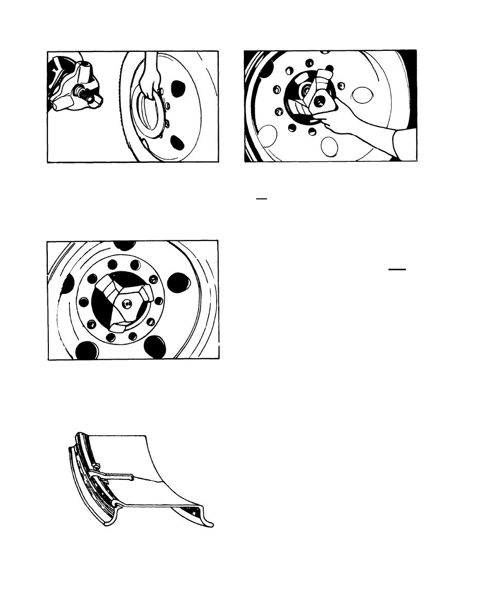
8. ALUMINUM AND REVERSE DISC DROP CENTER ASSEMBLIES
B. Position the shaft through the center hole of the
A. These wheels must be chucked from the disc side
wheel and spin on the special reverse disc cone with
and the tire must be demounted and mounted from the
opposite side. To do this, remove the chuck rods and
the flat side toward the chuck.
nut and install the steel backing ring on the outside
of the disc with the spring clips positioned through
the bolt holes as shown above.
C. Line up the arms of the cone directly o v e r the
bosses on the chuck casting and tighten the chuck to
300 Ibs.
NOTE: After the wheel is chucked, the remounting
and mounting operations are identical to the
standard tubeless assemblies, (See pages 5 -
7) except that in place of the offset press
wheel arm, the straight arm (part #9546) is used.
KW OR KB SPLIT RIMS
9.
A. The diagram at left is a cut-away view. To service
this rim, follow these steps:
1. Chuck the rim using the standard chuck rods.
(Be very careful not to over-tighten chuck, as
this rim has very little support on the side oppo-
site the lock ring.)
2. Break both beads and lubricate beads.
3. Remove assembly from machine.
4. Remove lock ring.
5 The assembly can now be easily taken apart
on the floor.
18
