
C4
TM 9-4935-481-14-1
Table 3-12. Battery Charging Procedure
Table 3-12. Battery Charging Procedure
STEP
UNIT
PROCEDURE
CORRECTIVE ACTION
STEP
UNIT
PROCEDURE
CORRECTIVE ACTION
Perform TTS Performance Test prior to this procedure.
NOTE
1
Prepare the DMS-D for testing per paragraph 2-6.
The major units and panels will be identified by the initials as indicated below.
2
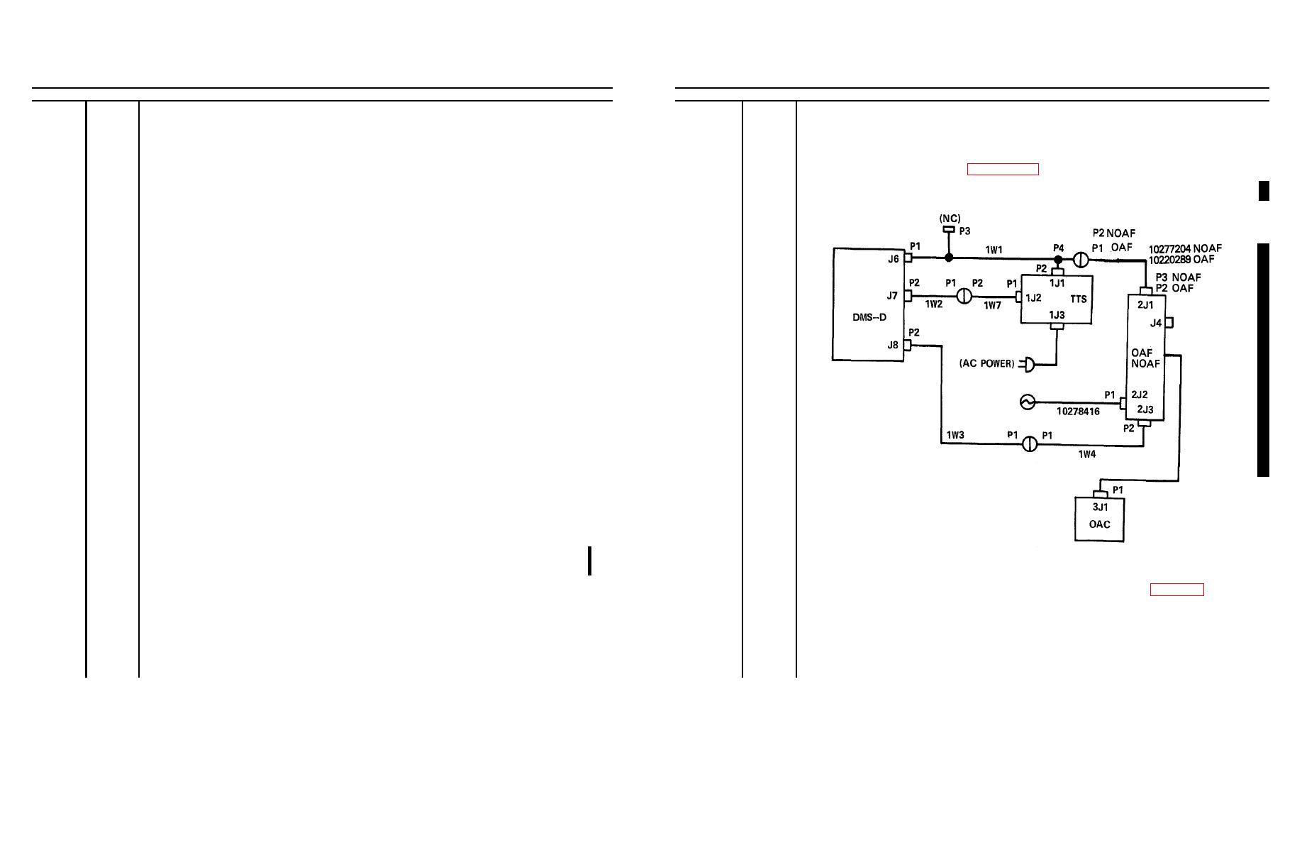
Prepare the TTS/TSG for testing per TM 9-4935-484-14, and connect the cables as depicted
DMS-D
3
below.
DMM
DIGITAL MULTIMETER
CT
COUNTER-TIMER
PP
POWER panel
MCP
MONITOR/CONTROL panel
CIP
COUNTER INHIBIT(SEC) panel
PPE
PROG PERFORM EVAL panel
TPS
TRIGGER PULSE SIM panel
TP
TRAINER panel
HWS
HORIZ WIRE SIM panel
TTS
TRACKER TEST SET
OAC
OPTICAL ALIGNMENT COLLIMATOR
OAF
OPTICAL ALIGNMENT FIXTURE
OSC
OSCILLOSCOPE (AN/USM-338)
RAD
RADIOMETER
4
TTS
Loosen the 24 captive screws securing the UUT to the UUT base and raise the panel. Loosen
TSG
TEST SET GROUP
the two screws securing the cover over the PC CARDS and raise it, allowing it to engage the
hook behind the front panel to support the front panel. Loosen the bolt on the TTS thermistor
NOAF
NIGHT OPTICAL ALIGNMENT FIXTURE
bracket and fasten the thermistor cable probe to the bracket as shown in figure 3-36.1. Tighten
the bolt on the thermistor bracket.
NOTE
No corrective action steps are indicated, as any faults should appear in the TTS
performance test.
3-205
