TM 9-4935-481-14-1
Table 3-20. IR Transmitter Performance Test
Table 3-20. IR Transmitter Performance Test-Continued
STEP
UNIT
PROCEDURE
CORRECTIVE ACTION
STEP
UNIT
PROCEDURE
CORRECTIVE ACTION
Determine the meter voltage from the graph in fig. 3-39 and
MCP
55
OSC
Establish a ground reference on the oscilloscope, and measure the
65
record this value for use in step 70.
least positive voltage in respect to ground. Record this value for use
in step 56.
DMM LO switch to EXT.
66
MCP
Multiply the value recorded in step 51 by the value recorded in step
56
DMM INPUT switch to DMM input.
55. The result should be 300 + 30 watts.
67
BTA
Refer to TM 9-6920-483-34-2
Connect the DMM pos probe to the LAMP CURRENT (+)
68
BTA
jack.
MCP
SELECTOR A switch to C10.
57
Connect the DMM neg probe to the LAMP CURRENT (-)
69
PSM
DMM
Adjust the external power supply to a reading of +27.00 + 0.30 Vdc.
58
jack.
Repeat steps 51 through 62.
59
Adjust R37 on the power control card to the value recorded
70
DMM
in DMM step 65, + 0.0150 Vdc.
Refer to TM 9-6920-483-34-2
MCP
SELECTOR A switch to C10.
Check Q12, Q13, VR5, and R37.
60
71
PSM
61
DMM
Adjust the external power supply to a reading of +24.00 + 0.50 Vdc.
Verify that the OPERATING RANGE meter is between the
operating limit lines.
MCP
SELECTOR B switch to C5.
Refer to TM 9-6920-483-34-2
62
72
PSM
OSC
Adjust the variable SWEEP control until only one cycle is displayed.
CB1 switch to OFF.
63
73
OSC
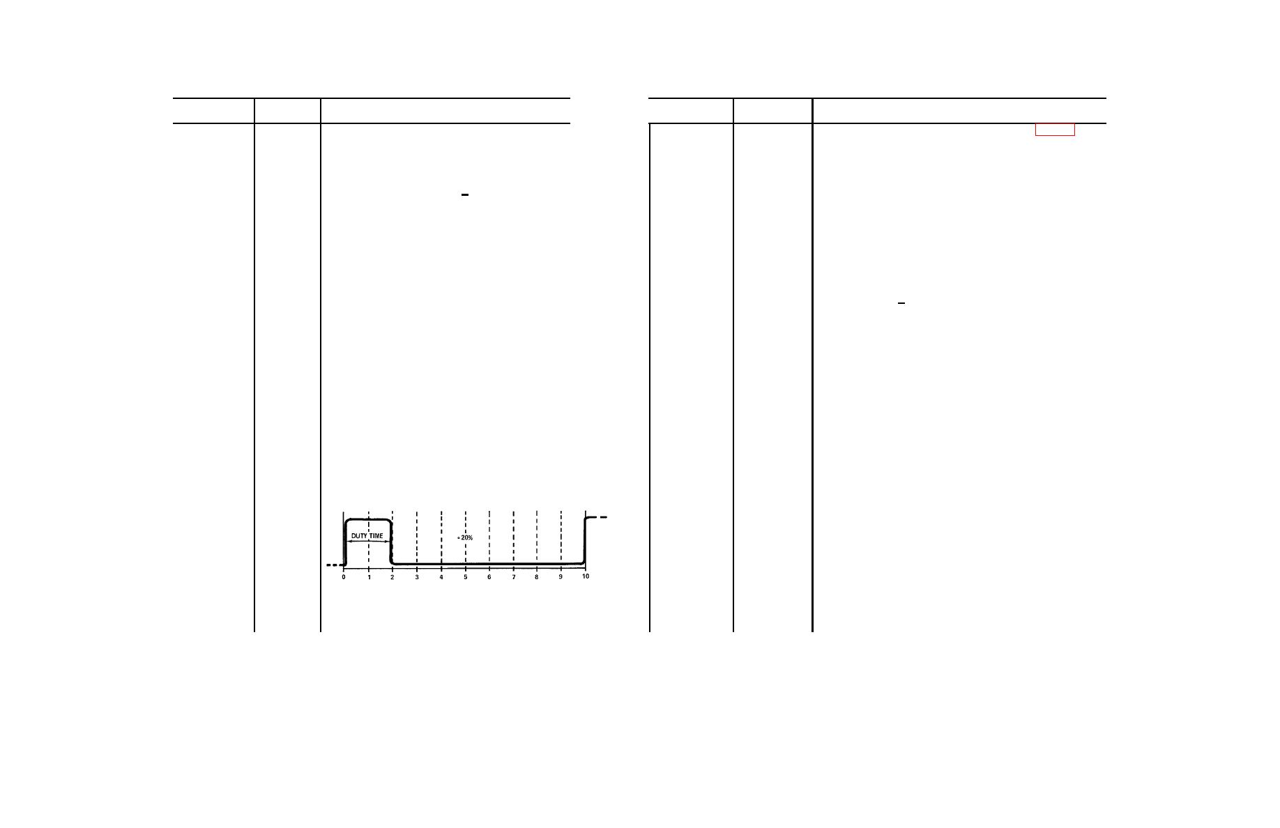
Measure the width of the positive pulse displayed (in centimeters)
Turn the external power source to OFF.
64
and divide the result by the total width of the cycle displayed
74
PP
(also in centimeters). Multiply the result by 100 and record this
MAIN POWER and DMS switches to OFF.
value as the duty cycle expressed as a percentage.
75
Disconnect and stow all test leads and accessories.
3-328


