
(a) Be sure the battery on-off switch
(35-A, fig. 16) of the pile flutter
circuit instrument panel (35, fig.
(22) and the ignition switch (IGN
SW) (7, fig. 15) are both in the
(e) Connect the lead from the positive
"ON" position. Place the 40-ohm
30-ampere
pile flutter binding posts, (d) above,
maximum
rheo-reg
switch (21) in the "REG" position.
to the No. G+ binding post (10-C,
(b) T u r n the speed control handle
(24) slowly clockwise until 1,000
tive pile flutter binding post, ( d )
rpm are indicated on the tachom-
above, to the No. F-B binding post
eter indicator meter (3).
(10-G, fig. 15).
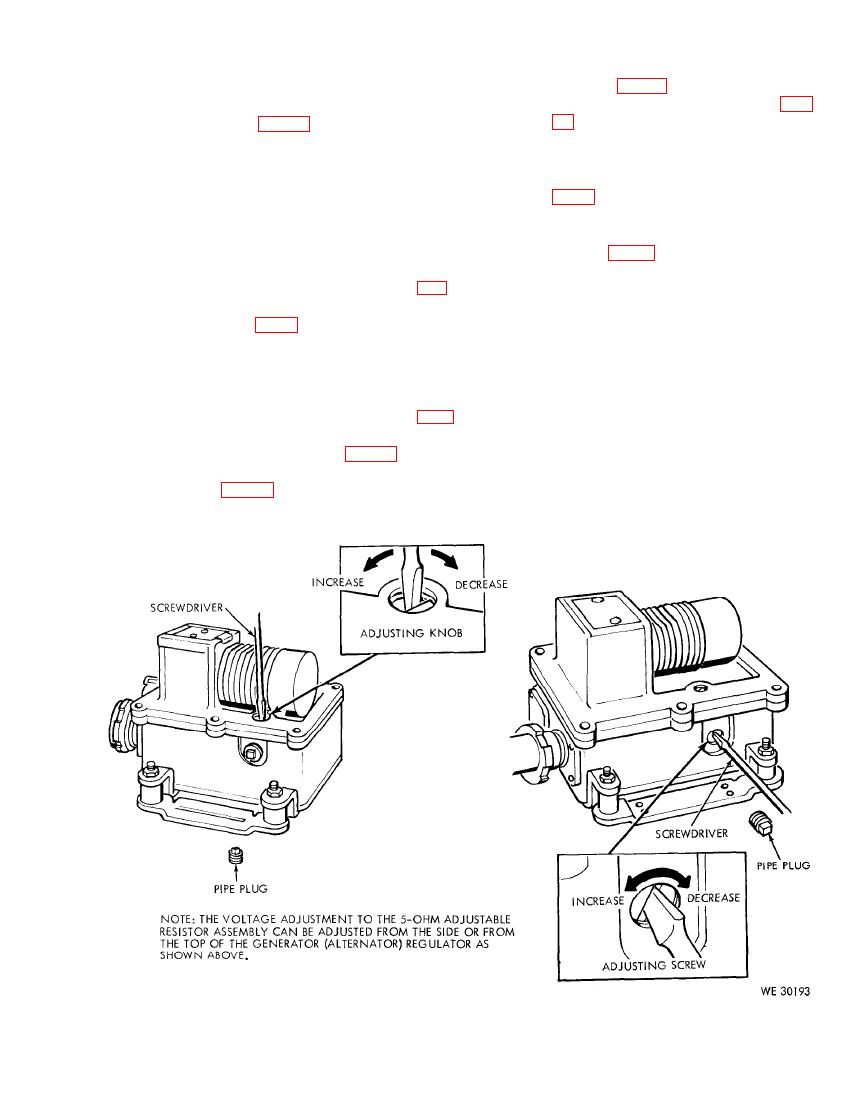
(c) Turn the knurled adjusting knob of
(f) Detect the action on the carbon
pile flutter of the generator (alter-
the 5-ohm adjustable resistor (fig.
56) (access through top cover of
nator) regulator by listening with
the headset. The sound should be a
regulator) (fig. 57) fully counter-
distinct hum.
clockwise (full increase) and ob-
serve the dc voltmeter (4) to assure
(g) Adjust the ampere fixed load by
placing all fixed load switches (17)
that it is in the safe range below
in the "OFF" position and the vari-
32 volts.
able load 0-25 0-12.5 ampere rheo-
stat (19) in the full counterclock-
74) to the positive and negative
wise position; then place the 50-25
binding posts (35-B, fig. 16) and
fixed load switch (17-B) in the
plug the lead of the electrical head-
"ON" position. Increase the rpm
set (fig. 65) into the phone jack
117

