phone connecting cord
plug
to
PHONE 4 jack (fig. 11).
TT-76(*)/GGC
(3) Connect the other TA-312/PT's tele-
phone connecting cord plug to
a. Remove the wooden shipping base and the
PHONE 1, 2, or 3 jack (fig. 12 and
dust cover from the TT-76(*)/GGC (TM
13) as desired.
11-2225).
b. Place the TT-76(*)/GGC in position on
the table top. Align the holes in the TT-
TH-5/TG
76(*)/GGC base with the holes in the table-
( fig. 13 and 23)
top. Secure the TT-76(*)/GGC in place with
the nuts and bolts provided; attach the nuts
a. Installation.
at the underside of the tabletop.
(1) Remove the TH-5/TG front panel
c. Perform the appropriate preinstallation
and chassis assembly from its case
services, and preparation for starting pro-
(TM 11-5805-246-10) .
cedures (TM 11-2225).
(2) Remove the spare fuses from the
cover assembly and store the fuses in
a storage cabinet.
d. Replace the dust cover on the TT-76(*)/
GGC and fasten the web strap across the top
(3) Turn the TH-5/TG chassis over and
of the dust cover.
check to see that the bare strap is
e. Insert the TT-76(*)/GGC gray, black,
connected between terminals D2 and
and red teletypewriter connecting cord plugs
F2. Connect a strap between the
into the TT-76 TD, TT-76 TR, and TT-76
terminals if none is provided.
REC jacks, respectively, on the teletypewriter
(4) Install each TH-5/TG in the TG-
patch panel (fig. 13 and 20). Set the cords
5/TG equipment rack by lifting the
into the associated cord clip.
designation plate on the rack; slide
the TH-5/TG into the rack and
tighten the captive screws to secure
TT-4(*)/TG's
the chassis in position.
b. Connection.
a. Perform the appropriate service proced-
(1) Connect the appropriate wire pair to
ures upon receipt of equipment (TM 11-5815-
the TH-5/TG 2W binding posts ac-
206-12) .
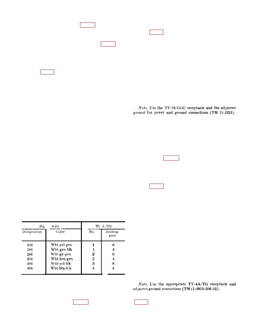
cording to the following chart:
b. Remove the wingnuts from the under-
side of the TT-4(*)/TG tabletop (TT-4(*)/
TG No. 1) or mounting shelf (TT-4(*)/TG
No. 2) and remove the retaining bars.
c. Position the TT-4(*)/TG on the table-
top or mounting shelf. Place the retaining
bars in the packboard lashing hooks on the
TT-4(*)/TG and through the holes in the
tabletop or mounting shelf.
d. Replace and tighten the wingnuts.
e. Perform the appropriate preliminary in-
stallation and final installation procedures (TM
.--
11-5815-206-12).
(2) Connect the TH-5/TG power cord
connector into the associated re-
t. Use the teletypewriter connecting cords
ceptacle on the TH-5/TG subdistri-
bution panel (fig. 12 and 21).
24

