
TM 11-5895-463-15
Section Ill. DIRECT SUPPORT, GENERAL SUPPORT,
AND DEPOT MAINTENANCE
to shelter. Refer to TB SIG 354 for further in-
formation on general support maintenance of
Support Maintenance
the shelter facility.
a. General. Direct and general support
maintenance consists entirely of corrective
c. Removal of Signal Entrance Box 26-Pair
maintenance procedures as indicated in the
maintenance allocation chart (appx C).
(1) Remove the screws that secure the
cover to the rear of the signal entrance box
b. Tools and Test Equipment Required. The
(fig. 4-15).
tools and test equipment required for direct
(2) Remove the cover from the defective
and general support maintenance of the AN/
26-pair receptacle.
MSC-31A are listed in the maintenance alloca-
(3) Remove the mounting screws that
tion chalt (appx C).
secure the insert clip to the housing.
(4) Unfasten the cable clip that secures
the cable form.
a. Radiofrequency and Direct Line Com-
Caution: Be extremely careful when
munications Equipment Repair. Refer to the
connecting and soldering wires to the recep-
applicable technical manual (appx A) for in-
tacle insert. Excessive heat or pressure will
in performing direct support
structions
damage the receptacle insert.
m a i n t e n a n c e of the TA312/PT, SB-22A/
(5) Lift the receptacle insert out of the
P T , LS-147C FI, AN/VRC-47, AN/GRR-5,
housing; tag and unsolder the wires.
and Air Condition Model F9002.
(6) Remove the mounting screws and re-
move the housing.
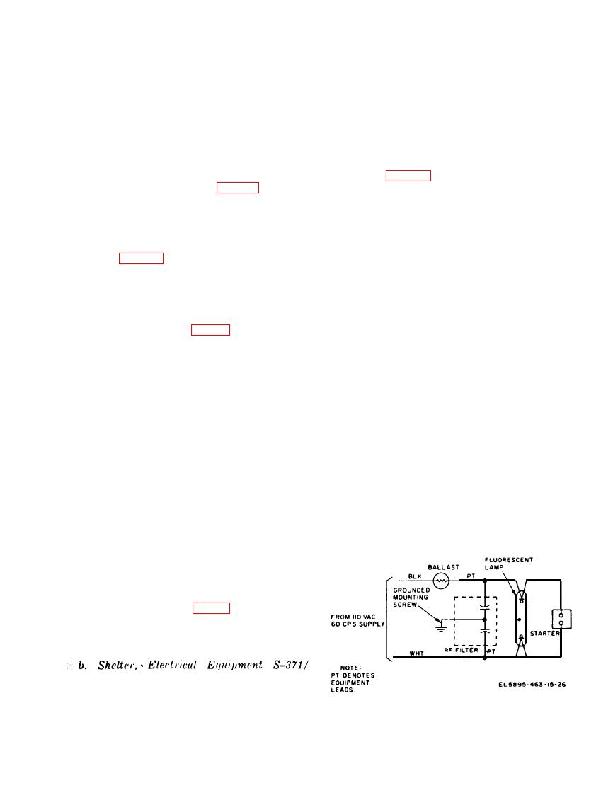
b. Shelter, Electrical Equipment S 3 7 1 /
ISC-31A Repairs. Direct support repair of
d. Replacement of Signal Entrance Box 26-
the S-371/MSC-31A includes the following:
Pair Receptacle (fig. 4-15).
( 1 ) Emergency repairs of holes and
(1) Position the housing and secure it to
minor structural damage to the shelter.
the signal entrance box.
(2) Removal and replacement of the door
Caution: Be extremely careful when
handle and latchbolt assemblies, entrance door
connecting and soldering wires to the recep-
filter, cover assemblies, and gaskets for the
tacle insert. Excessive heat or pressure will
blower vent, door, and the entrance boxes.
damage the receptacle insert.
Note. Refer to TB SIG 354 for additional in-
(2) Slide the end of the cable form out
of the
f o r m a t i o n on direct support maintenance
through the housing and connect the wires to
shelter.
the receptacle insert.
a. Radiofrequency and Direct Line Com-
munications Equipment Repair. Refer to the
applicable technical manual (appx A) for in-
structions on performing general support
maintenance on the communications equipment
in the assemblage.
SC-31A Repair. General support mainte-
ance of the S371/MSC31A includes re-
placement of doors and skids, and permanent
repair of holes and major structural damage
diagram.
