
TM 55-1925-283-12&P
OPERATOR AND UNIT MAINTENANCE
FUEL FILTER/WATER SEPARATOR (FUEL TRANSFER SYSTEM) FOR
INLAND AND COASTAL LARGE TUG (LT)
DESCRIPTION AND USE OF OPERATOR CONTROLS AND INDICATORS
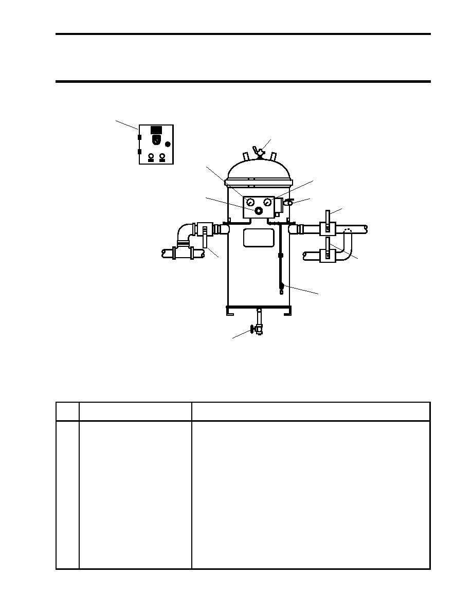
FUEL FILTER/WATER SEPARATOR
1
2
11
3
10
4
5
9
6
7
8
Figure 1. Fuel Filter/Water Separator
Table 1. Fuel Filter/Water Separator (refer to figure 1)
Key
Control/Indicator
Function
1
Control Panel
This control panel contains the ON/OFF switch and fuses for the
fuel filter/water separator. Refer to figure 2 for details.
2
Vent Valve
This valve permits the operator to vent air from the fuel filter/water
separator during priming.
3
Discharge Pressure Gauge
This gauge indicates the pressure or vacuum present on the dis-
charge side of the fuel filter/water separator.
4
Upper Ball Valve
This valve permits the operator to drain the upper portion of the fuel
filter/water separator assembly prior to changing filters.
5
FO-17 F.O. FLTR / WATER
This valve secures the fuel exiting the fuel filter/water separator.
SEP OUTLET COV
0004 00-1
