
TM 55-1925-284-14&P
0016 00
1
2
2
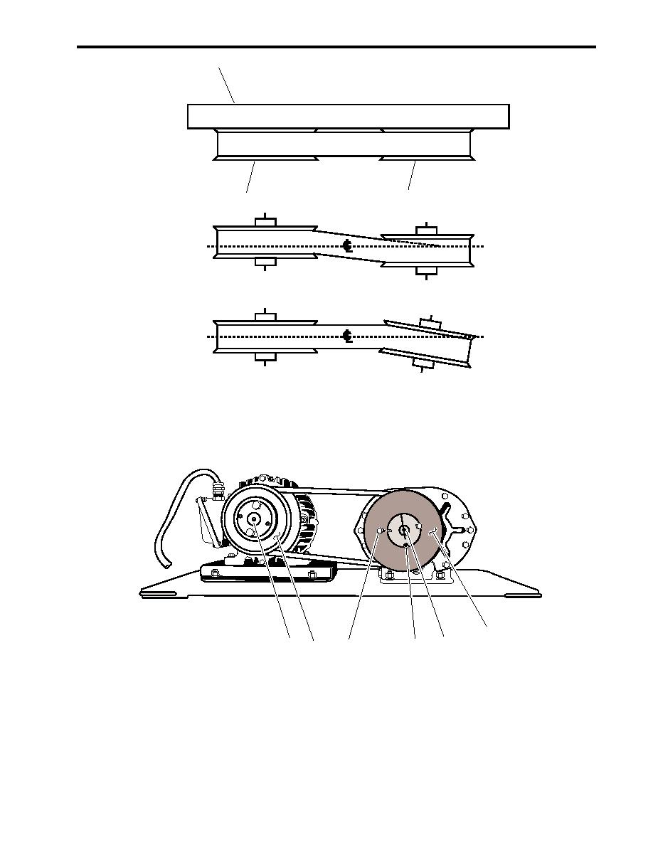
Proper Alignment
Parallel Misalignment
Angular Misalignment
Figure 3. Sheave Alignment
2
4
6
3
1
5
Figure 4. Blower Sheave Removal
ASSEMBLY
1. Position the blower sheave (figure 4, item 2) on the blower shaft (figure 4, item 4) so that the suitable straight
edge (figure 3, item 1) rests against the machined surfaces of the blower sheave (figure 4, item 2) and the
motor sheave (figure 4, item 5). Ensure that the suitable straight edge is perpendicular to the blower shaft
(figure 4, item 4) and the motor shaft (figure 4, item 6) while making contact with the blower and motor
sheaves.
0016 00-5
