
TM 55-1925-284-14&P
0016 00
INSTALLATION
1. Install a new belt (figure 1, item 10) on the blower sheave (figure 1, item 12) and the motor sheave (figure 1,
item 11).
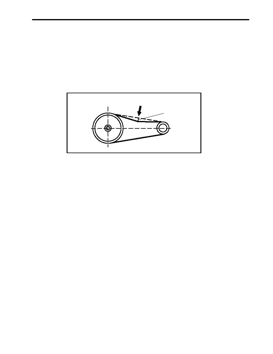
2. Slide the motor (figure 1, item 7) away from the blower (figure 1, item 9) until the proper belt tension is
achieved. Proper tension is achieved when the belt may be deflected 1/2 inch (13 mm) at its midpoint
(figure 2) when applying approximately 4 to 5 pounds (1.8 to 2.3 kg) of force to the belt. A new belt
should be tensioned tighter (approximately 3/8 inch (10 mm) deflection).
DIREC
T
FORCE ION OF
APPLIE
D
DEFLECTION
(Inches)
Figure 2. Belt Adjustment
3. Tighten the four bolts (figure 1, item 6).
4. Perform the Sheave Alignment procedures in this work package.
5. Check the belt tension several times during the first 50 hours of operation. Adjust if necessary. Use the
procedure detailed in step 2 above for checking tension and adjusting the belt.
6. Position the belt guard (figure 1, item 4) over the studs (figure 1, item 3) on its base (figure 1, item 5) and
secure it with the four nuts (figure 1, item 1) and four new lockwashers (figure 1, item 2).
7. Perform the Follow-On Service procedure at the end of this work package.
BELT ADJUSTMENT
DISASSEMBLY
1. Remove the four nuts (figure 1, item 1) and four lockwashers (figure 1, item 2) from the studs (figure 1,
item 3) that secure the belt guard (figure 1, item 4). Discard the lockwashers.
2. Remove the belt guard (figure 1, item 4) from its base (figure 1, item 5).
3. Loosen, but do not remove, the four bolts (figure 1, item 6) that secure the motor (figure 1, item 7) to its base
(figure 1, item 8).
4. Slide the motor (figure 1, item 7) towards the blower (figure 1, item 9) until the belt (figure 1, item 10) is loose
enough to be removed from the motor sheave (figure 1, item 11) and the blower sheave (figure 1, item 12).
0016 00-3
