
TM 55-1925-284-14&P
0028 00
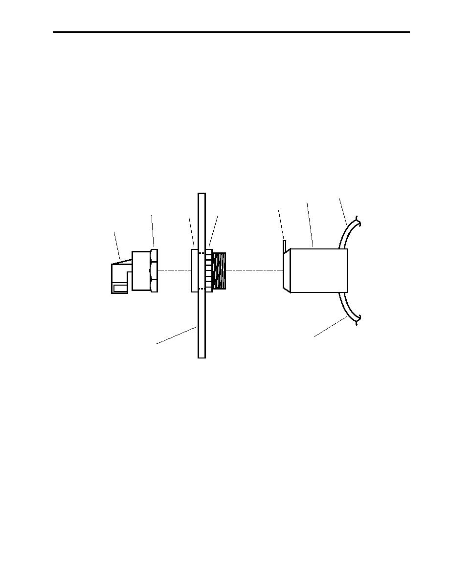
ROTARY SWITCH REPLACEMENT
REMOVAL
1. Perform the Open the Controller procedure at the beginning of this work package.
2. Unscrew the retaining ring (figure 3, item 1) and pull off the knob (figure 3, item 2).
3. Label and disconnect the wiring (figure 3, item 3) from the contactor (figure 3, item 4).
4. Lift the locking tab (figure 3, item 5) slightly and disconnect the contactor (figure 3, item 4) from the actuator
(figure 3, item 6).
5. Remove the retaining nut (figure 3, item 7) and remove the actuator (figure 3, item 6) from the door (figure 3,
item 8).
3
4
5
1
7
6
2
3
8
Figure 3. Rotary Switch Replacement
INSTALLATION
1. Install the actuator (figure 3, item 6) in the door (figure 3, item 8) and secure it with the retaining nut (figure 3,
item 7).
2. Install the contactor (figure 3, item 4) on the actuator (figure 3, item 6) with the locking tab (figure 3, item 5)
facing upward.
3. Connect the wiring (figure 3, item 3) to the contactor (figure 3, item 4) using the labels from step 3 in Removal
as a guide. Remove the labels.
4. Install the knob (figure 3, item 2) on the actuator (figure 3, item 6) and secure it with the retaining ring
(figure 3, item 1).
5. Perform the Follow-On Service procedure at the end of this work package.
0028 00-3
