TM 55-1925-284-14&P
0028 00
3. Open the controller door (figure 1, item 2).
WARNING
Replace or repair components only after the affected circuit has been secured,
locked out, and tagged out. Performing replacement with the circuit energized
may result in injury.
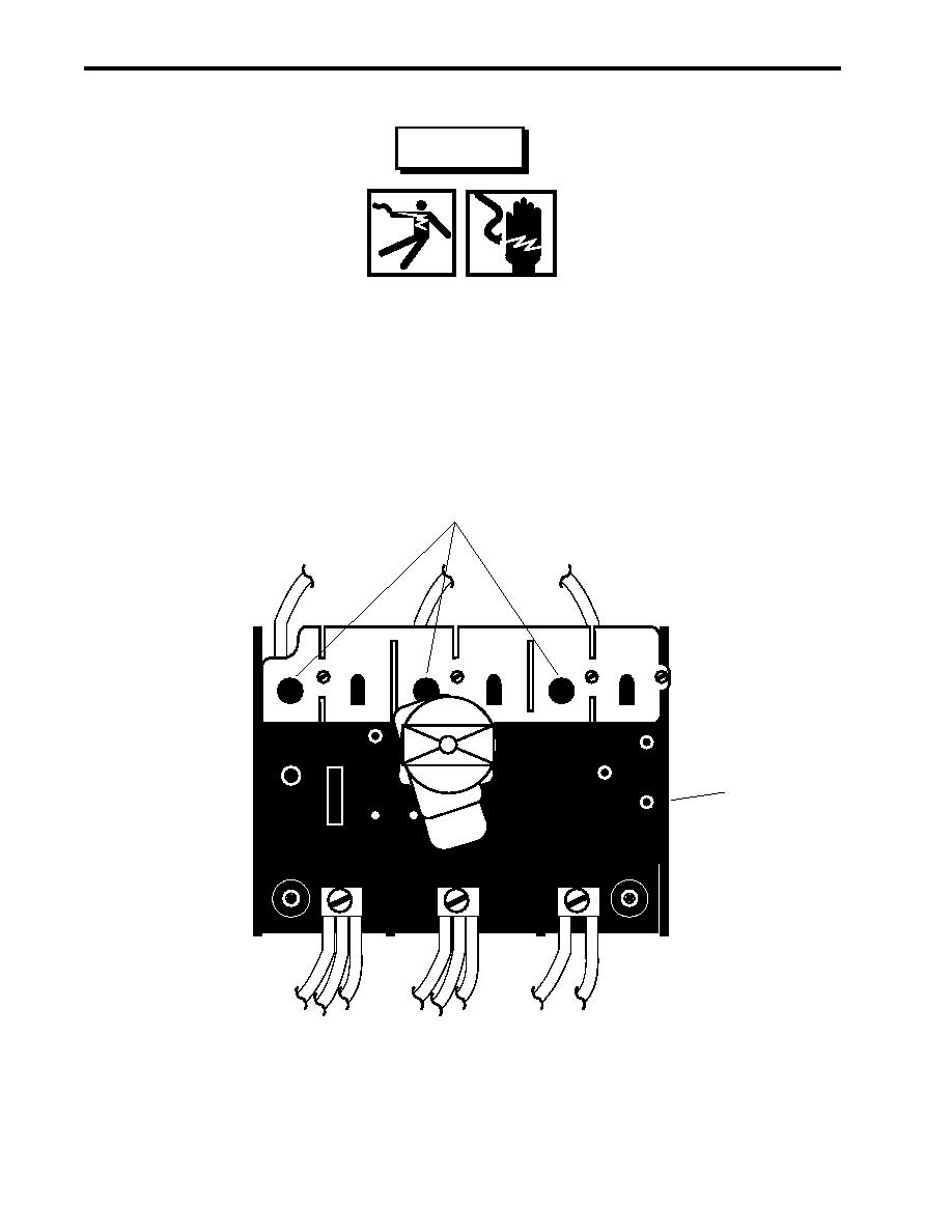
4. Use a multimeter to check for voltage at the line side (figure 2, item 1) of the interrupt contactor (figure 2,
item 2). If voltage is present, ensure that the proper breaker is secured, locked out, and tagged out (FM 55-
502). If no voltage is present, continue with the appropriate repair procedure below.
1
2
Figure 2. MSD Interrupt Contactor
0028 00-2

