TM 55-1925-286-13&P
0020 00
3
L2
T2
T1
L1
2
1
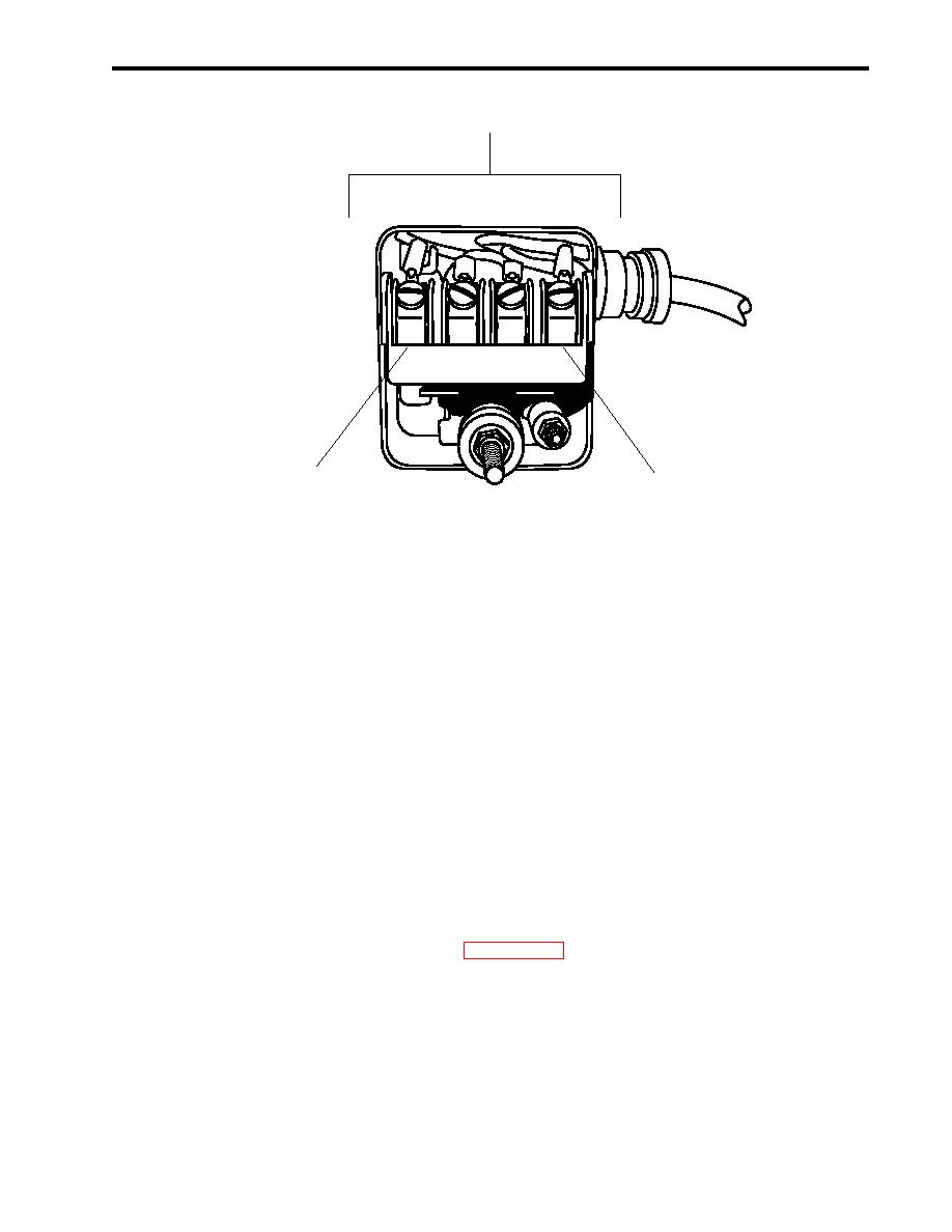
Figure 2. Pressure Switch
INSTALLATION
1. Contact direct support maintenance for installation of the removed compressor.
2. Connect the pressure tubing (figure 1, item 7) at its fittings (figure 1, item 8).
3. Connect the discharge steel braided flex hose (figure 1, item 5) to the compressor at its union
(figure 1,item 6).
4. Connect the wiring in the pressure switch (figure 2, item 3), L1 (figure 2, item 1) and L2 (figure 2, item 2),
using the labels from step 7 of Removal as a guide. Discard the labels.
5. Connect the motor wiring (figure 1, Item 3) using the labels from step 5 of Removal as a guide. Discard the
labels.
6. Remove lockouts and tagouts (FM 55-502).
7. Operate the compressor under usual conditions (WP 0005 00).
8. Observe that the compressor operates normally without any leakage, vibration, or unusual noise.
9. Return equipment to the desired readiness condition.
END OF WORK PACKAGE
0020 020304 -3lank
0 0- / 0 b

