TM 9-1550-416-14&P
CAUTION
(3) Connect the alligator clips of the external 12
Vdc emergency power cable to any appropriate source of 12
Be careful to observe proper polarity when
Vdc power being careful to observe proper polarity. The
connecting the power cable alligator clips to
alligator clips are color coded to indicate which is the positive
the 12 vdc power source.
connectar (red) and which is the negative connector (black).
(4) Resume operation of the GSE field box in the
(2) Connect the alligator clips of the external 12
same manner as when it was connected to its own source of 12
Vdc emergency power cable to any appropriate source of 12
vdc power.
Vdc power, being careful to observe proper polarity. The
alligator clips are color coded to indicate which is the positive
c. Perform the following procedures to use an external
connector (red) and which is the negative connector (black).
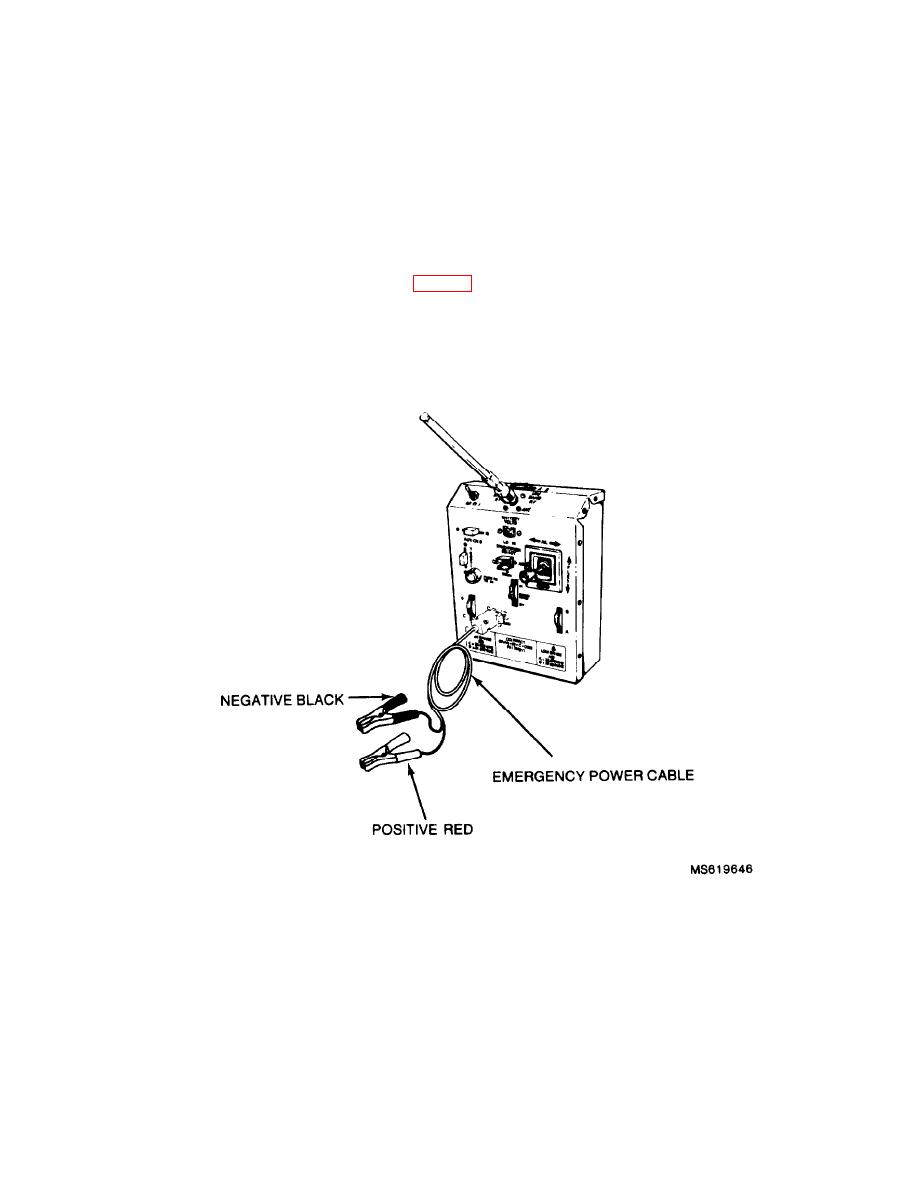
12Vdc power source to power the transmitter. (See fig. 2-37.)
(3) Resume operation of the transmitter in the
(1) Connect the external 12 Vdc emergency con-
same manner as when it was connected to its own source of 12
nector to the transmitter TRAINER/CHARGE/ EMER-
Vdc power.
GENCY connector.
Figure 2-37. External 12 Vdc emergency power cable operation of the transmitter.
2-39

