
TM 9-1550-416-14&P
4-3. DESCRIPTION AND USE OF OPERATOR'S FSU CONTROLS AND INDICATORS.
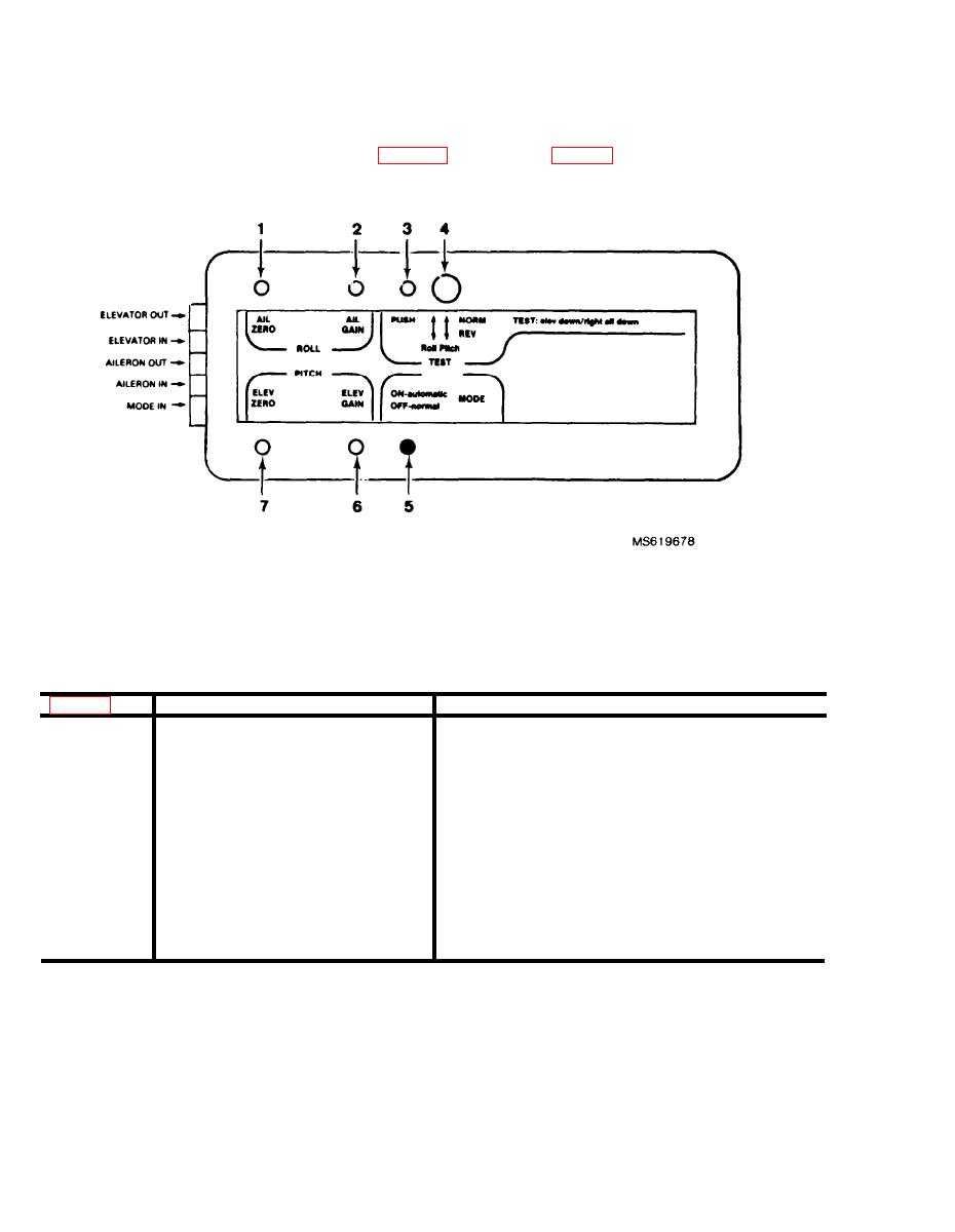
The controls and indicators of the FSU are illustrated in figure 4-2 and explained in table 4-1
Figure 4-2. FSU controls.
Table 4-1. FSU Contols and Indicators
Fig. 4-1 Key
Control or Indicator
Function
1
Used to align ailerons during FSU operation.
A.P. Zero
2
A.P. Gain
Used to increase or decrease aileron sensitivity during
FSU operation.
3
A.P. Test Button
Used to check FSU operation.
4
A.P. NORM/REV switches
Used to change the direction of operation of the FSU.
5
Mode LED
Shows operation of FSU.
6
A.P. Gain
Used to increase or decrease elevator sensitivity during
FSU operation.
7
A.P. Zero
Used to align elevator during FSU operation.
4-2
