TM 9-1550-416-14&P
CAUTION
(2)
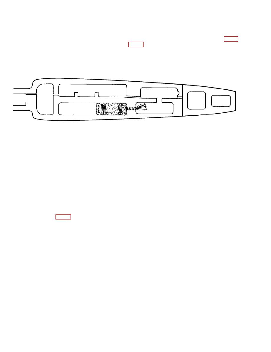
Install FSU. Place gyro assembly into fuselage
compartments and extend connectors through hole. (See fig.
Stabilizer is wrapped in foam packaging. Do not
install FSU without foam packaging.
pushing foam packaging aside.
MS619680
Figure 4-4. FSU installation.
Connect gyro electronics assembly to the receiver and
(d) Connect the ELE In connector on the gyro
(3)
servo/battery group. (See fig. 4-5.) Push aside the edge of the
control box to the elevator channel on the receiver.
foam packaging when making the connections.
(e) Connect the ELE Out connector on the gyro
(a) Connect the Mode In connector on the gyro
control box to the elevator servo connector.
control box to the AUX A channel on the receiver.
(f) Connect the throttle servo connector to the
throttle channel on the receiver.
(b) Connect the AIL In connector on the gyro
control box to the aileron channel on the receiver.
(g) Connect the battery connector to the re-
ceiver power plug on the receiver.
(c) Connect the AIL Out connector on the gyro
control box to the aileron servo connector.
4-4

