
TM 9-1550-416-14&P
Section II. AUXILIARY EQUIPMENT ASSEMBLY AND PREPARATION FOR USE
b. Perform assembly steps 1 through 19 of paragraph 3-
4-4. UNPACK FLIGHT STABILIZATION KIT.
NOTE
c. Perform FSU installation procedures as outlined be-
low.
Do not remove components from foam packaging.
NOTE
a. Open container and remove stabilizer.
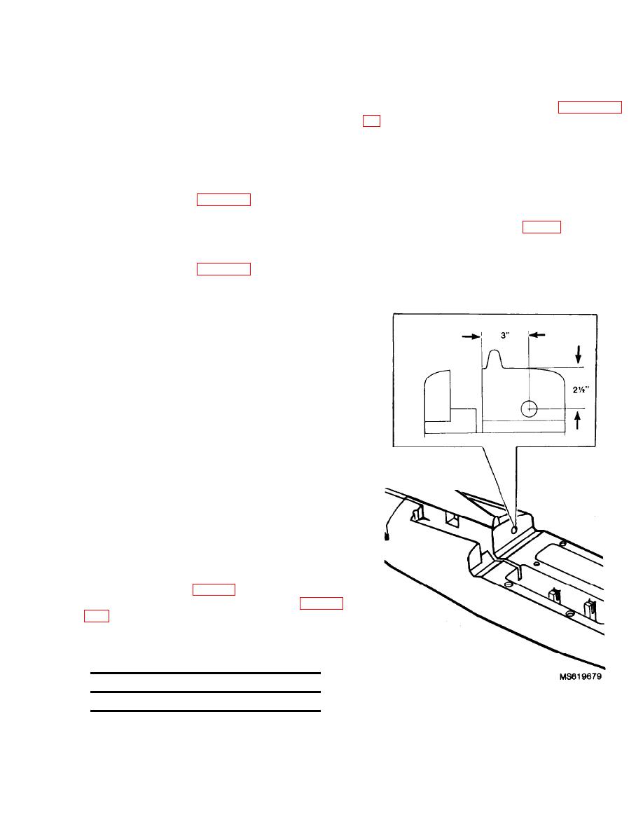
In order to install the FSU, a section of the fuselage
must be modified.
Modify fuselage. (See fig. 4-3.)
UNPACK FIELD SUPPORT KIT.
4.5.
(1)
(a) Locate a point 2.5 inches from the top
a. Open container and carefully remove contents.
and 3.0 inches from edge of the flight control compartment.
(b) Cut a hole approximately 1 inch in
diameter in the front bulkhead of the receiver compartment
c. Storage of field support kit contents is the responsibil-
using the point located above as the center point.
ity of the using unit; however, care in storage should be taken
for the following items.
Engine
Receiver and servo/battery group
Epoxy
INSTALLATION OF FLIGHT STABILIZA-
4.6.
TION UNlT (FSU).
a. Procedures for FSU installation depend upon the stage
of assembly of the target.
b. Installation of the FSU during assembly is accom-
plished by performaing installation instructions during the
initial procedures.
c. Installation of the FSU in an assembled target is accom-
plished by partially disassembling the target, installing the
FSU, and reassembling it.
FSU INSTALLATION DURING TARGET
4-7.
ASSEMBLY.
steps outlined below. (For FSU item identification, see figure
Table 4-2. FSU Assembly Components
Item
Quantity
1
Gym Control Box
Figure 4-3. Hole for FSU connectors
into receiver compartment.
4-3
