
TM 9-2330-271-14&P
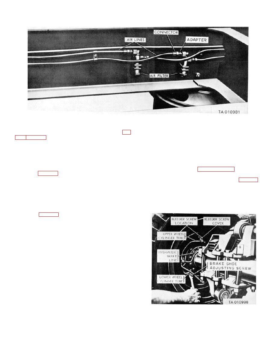
Figure 4-25. Air lines and air filters (some models).
k. Emergency Air Line. The emergency air line (fig.
(2) Place jack under axle and raise rear of
semitrailer until tires clear ground.
b. Adjustment
EMERGENCY) along the inside of the left side rail,
through an air filter (on some models) and into the
NOTE
bottom of the relay valve assembly It transmits
Try to laterally rock wheel, hub and
compressed air to fill the air reservoir and to maintain the
brake drum assembly on axle spindle
proper air pressure under the control of the relay valve.
If rocking condition prevails, adjust
I.
Air Filters Some model semitrailers incorporate
wheel bearings (paragraph 4-47f(6))
air filters (fig. 4-25) connected into the air lines at the
before making brake adjustment.
midpoint of the chassis frame to prevent moisture or
(1) Turn brake shoe adjusting screw (fig 4-26),
foreign matter from passing through the air lines
located at top rear face of brake backing plate, clockwise
Removable elements, held in place by spring washers
to expand the front brake lining in contact with brake
and compression springs, are removed by unscrewing a
drum until brakes drag slightly when wheel or drum is
cap nut. A square head pipe plug in the cap nut is
turned by hand.
removed to drain any moisture.
(2) Back off adjusting screw just enough to
m. Wheel Brake Mechanism. Each wheel brake
allow drum to rotate freely.
mechanism (fig. 4-24), located within the brake drum and
supported by a brake backing plate, has two brake shoes
fitted with brake linings. Two hydraulic cylinders are
mounted between the ends of the shoes. Slotted piston
rods in each end of the cylinder engage with slots in the
end of each brake shoe. Hydraulic pressure forces the
cylinder piston outward to apply the brake linings to the
drum Two brake retracting springs draw the shoes away
from the drums when hydraulic pressure is not applied
and hold it in the retracted or released position.
4-32.
Brake Adjustment
a.
Preliminary Steps.
(1) Release pressure from braking system by
opening drain cock on air reservoir.
Figure 4-26. Brake adjustment.
4-40
