TM 9-2330-271-14&P
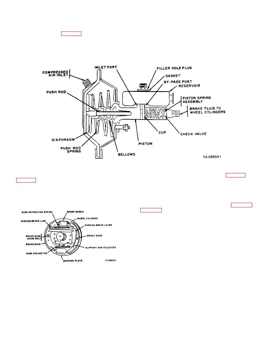
mounted on a bracket under the center of the dolly,
piston inside the master cylinder. The piston is actuated
forward of each axle (fig. 4-46). The master cylinder
by pressure from the push rod to create hydraulic
converts movement of the brake air chamber push rod
pressure in proportion to the pressure applied by the
into hydraulic pressure to apply the brakes. The air
push rod. Rubber bellows protect the push rod and
chamber push rod contacts a
piston end from foreign matter.
Figure 4-23. Brake hydraulic master cylinder.
i.
Air Reservoir. The air reservoir (fig. 4-22), a
h. Hydraulic Wheel Cylinders. Two wheel cylinders
metal tank located on the center of the dolly over the rear
the shoes outward to force the brake linings against the
axle, stores compressed air used to apply the semitrailer
brake drums. Each wheel cylinder is connected to the
chassis brakes. The reservoir is equipped with a drain
hydraulic master cylinder with tubing and is fitted with a
cock for draining moisture and releasing air pressure if
bleeder valve at the rear to permit air to be bled from the
the brakes are locked.
j.
Service Air Line. The service air line (figs. 4-21
system.
SERVICE) along the inside of the front rail, and along the
inside of the right side rail, into the top of the relay valve
assembly. It transmits changes in the air pressure which
cause the relay valve to function. These changes result
from the brake pedal in the towing vehicle being
depressed or released.
Figure 4-24. Wheel brake mechanism.
4-39

