
TM 9-2330-271-14&P
(6) While turning hub slowly, tighten inner
(8) Install outer bearing adjusting nut (6) using
bearing adjusting nut, using wheel bearing adjusting nut
wheel bearing adjusting nut wrench, drawing it up tightly
wrench, until hub binds on spindle. Back off nut about
against nut locking key washer (7). Do not disturb
one-eighth turn. Check adjustment by attempting to rock
bearing adjustment.
hub on spindle. If bearings are properly adjusted,
(9) Bend one or two locking lugs of key washer
movement of brake drum in relation to top edge of
(7) over outer and inner adjusting nuts (6).
backing plate will scarcely be visible and brake drum will
(10) Recheck wheel bearing adjustment ((6)
turn freely. If movement is excessive (more than one
above).
thirty-second of an inch), further adjustment is required.
(11) Position hub cap (4) and gasket (5) and
(7) Install nut locking key washer (7) on
secure with three screws (24) and washers. (23).
spindle.
(12) Adjust brakes (paragraph 4-32).
NOTE
With a minimum of movement, adjust
bearing adjusting nut (6) so that flats
of nut will mate with locking lugs on
key washer (7).
Section X. MAINTENANCE OF SPARE WHEEL CARRIER
(2) Check ratchet wheel (5) for wear and
4-48.
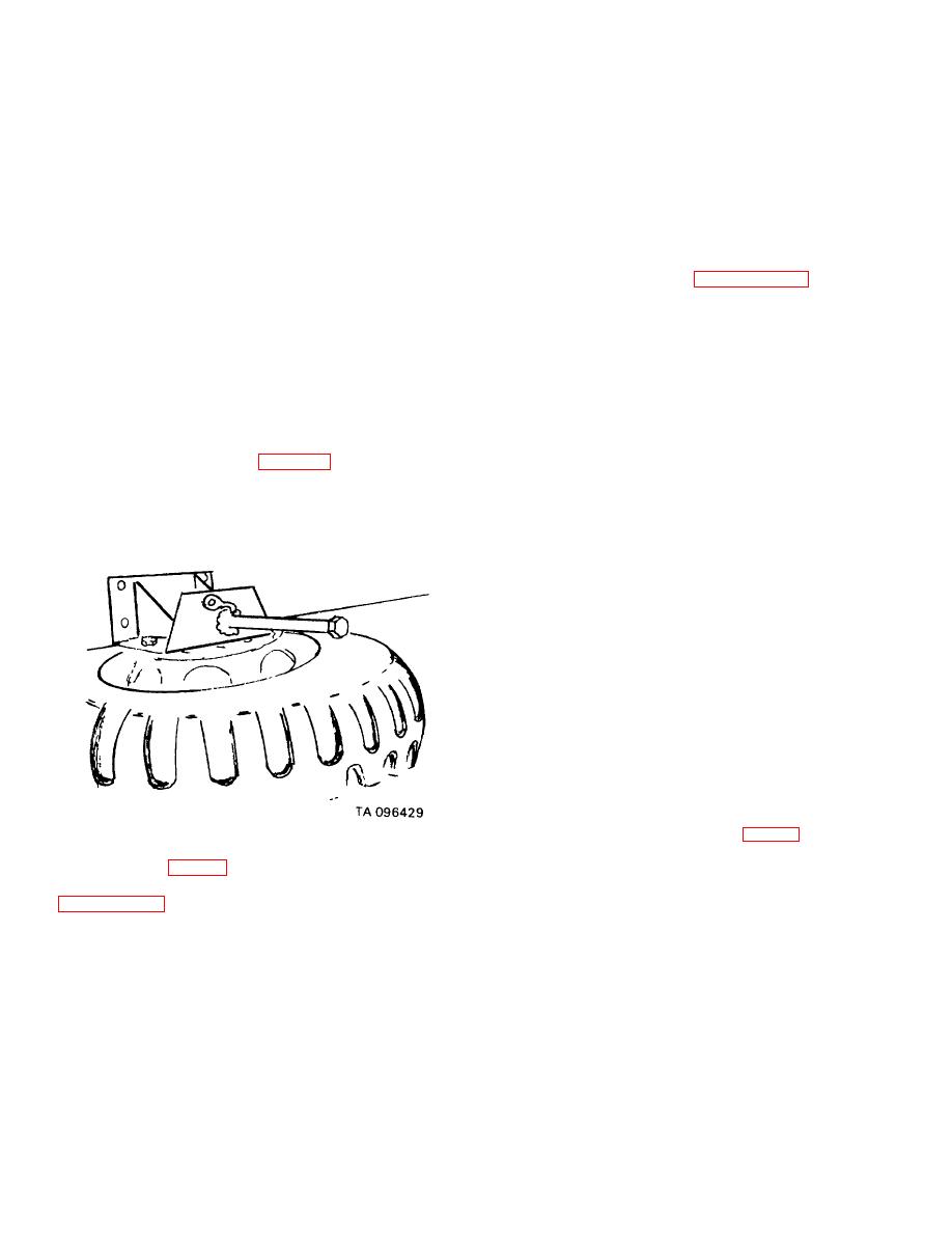
Spare Wheel Carrier (fig. 4-35)
alignment. Check weld of ratchet and nut on shaft for
cracks or undue teeth wear.
Reweld to shaft if
a. General. The spare wheel carrier is mounted on
necessary.
the side of the frame of the semitrailer chassis. The
(3) Replace ratchet wheel by removing cotter
carrier has a windlass to facilitate the raising and
pin (6) and wire rope (11). Slide worn ratchet wheel out
lowering of the spare wheel and tire.
and new one in; then secure with cotter pin (6) and
attach wire rope (11).
(4) Check pawl (14) for wear and looseness of
rivet (15) which attaches pawl to upper member.
Replace pawl and/or replace rivet if necessary.
(5) Check lower member (9) for dents or
twisted parts.
(6) Check U-bolts (10) for tightness. Check
attaching nuts (13) for stripped threads or looseness and
replace if necessary.
(7) Check wire rope (11) for frayed wire or
undue wear and replace if necessary (8) Repaint and
repair damaged surfaces where paint has been
removed.
Figure 4-35. Spare wheel carrier.
e. Replacement of Wire Rope (fig. 43).
(1) Release wire rope (11) from lower member (9) by
b.
Removal (fig. 43).
removing four nuts (13) and lock washers (12) from U-
(1) Remove spare wheel and tire from carrier
bolts (10).
(2) Draw wire rope (11) from holes in shaft.
(2) Remove four nuts (1), lock washers (2) and
(3) Make a wire rope with ferrules to prevent
screws (3) securing carrier to mounting bracket.
raveling, from 6 feet of three-sixteenths of an inch
(3) Remove carrier.
diameter, 7 by 19 aircraft type, preformed wire rope.
c. Cleaning. Remove all surface dirt with water and
(4) Thread through holes in ratchet wheel (5)
stiff brush.
until both ends are of equal length.
d. Inspection and Repair.
(5) Cross ends of wire rope under lower
(1) Check upper member (7) for cracks or
member.
breaks in welds. Straighten member and weld cracks.
(6) Twist ends in loose, single knot across
4-51
