TM 9-2330-294-14
(1) Reassemble each equalizer beam assembly
c. Cleaning. Clean all dirt and grease from
to axle in reverse order of removal (b (16), (17), and
suspension parts using dry-cleaning solvent type II
(18) above). Using torque Wrench (GGG-W-686)
(SD-2) and a stiff fiber brush.
torque beam-to-axle shaft nuts to 1,260-1,680 lb ft.
d. Inspection.
CAUTION
(1) Inspect parts for cracks, damage or wear.
Take care not to damage or fold over lips of
(2) Inspect torque rod rubber bushing for
grease seal when inserting equalizer beam
damage or deterioration.
center shaft.
(3) Inspect felt washers on beam-to-axle shaft
(2) Insert equalizer beam center shaft in center
for wear.
(4) Inspect axle shaft for fatique cracks around
housing of each equalizer beam.
bearing journals, shoulders and welded hanger
(3) Install remaining axle components in
reverse order of disassembly (b (9) through (14)
brackets or tapping pads.
above.
(5) Inspect journals for extreme wear or
scoring. No more than 10 percent of bearing surfaces
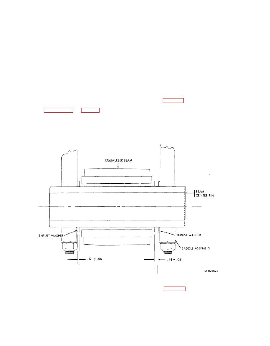
(4) With chassis raised, position front bogie
can be pitted or scored. Markings cannot be over
in place. Refer to figure 5-6 and aline bogie laterally
so that 0.44 inch gap exists on the inward side of
0.002 inches deep.
(6) See paragraph 6-6 and table 6-1 for repair
either beam. Use as many thrust washers as
standards for axle and equalizer beam.
required on the center pin to achieve this dimen-
e. Repair.
sion. This gap allows lateral travel along the beam
(1) Replace parts damaged or excessively worn.
center pin during certain suspension stress con-
(2) Replace axle member of damage is found.
ditions.
f. Installation.
(6) Refer to figure 5-5 and install each torque
(5) Secure left equalizer beam to saddle
rod on axle bracket with locking adapters through
assembly with four nuts and flat washers and
torque rod bracket leg holes and into torque rod end
tighten to 480 - 640 lb ft torque. Secure right
holes.
equalizer beam by same procedure.

