
TM 9-2330-356-14
with the piping schematic, mounted on the tool box cover,
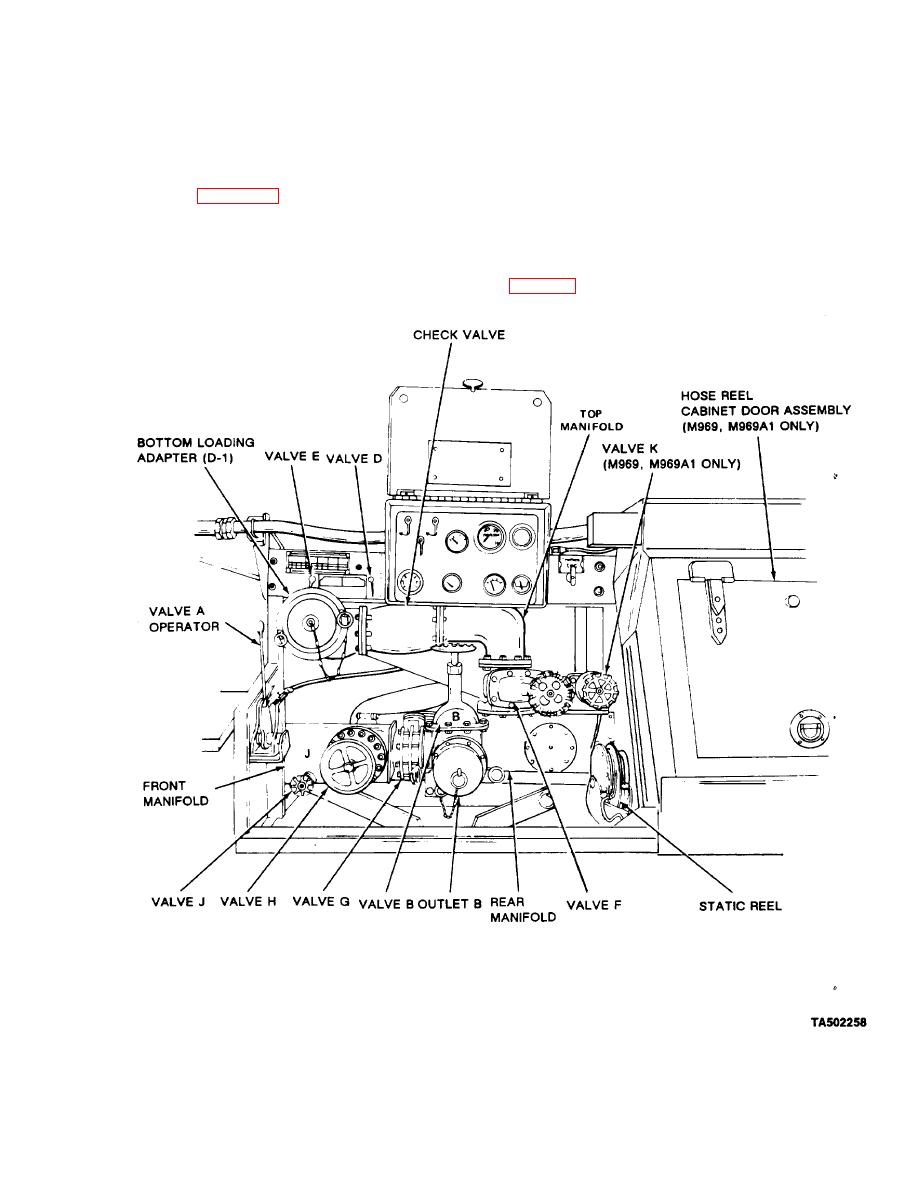
(2) Valve B (All Models). Fastened to the rear
for each model.
manifold. Controls the opening for bulk delivery
connections.
Piping Control Assembly. This assembly contains a
a.
(3) Valve C (M970, M970A1). Attached to the
4-inch pilot-operated control valve, plus the following
rear manifold. It is a check valve controlling the opening
components (figures 2-11 and 2-12):
for defueling operation.
(1) Valve A, Emergency Valve Operator (All
(4) Valve D, Precheck (All Models). Fastened to
Mode/s). Mechanically controls both the emergency valve
the frame above the piping control assembly. Provides a
on the outlet sump and the vapor vent on top of
way to check the shut-off float for proper functioning.
semitrailer.
(M969 and M969A1 Arrangement Shown).
