
TM 9-2330-356-14
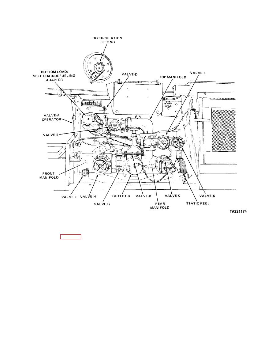
(11) Valve K (M969, M969A1, M970, M970A1). On
(5) Valve E (M967, M967A1, M969, M969A1).
the rear manifold. Allows fuel flow between the bulk
Located next to the precheck valve (D). Provides
delivery connections and the filtering/dispensing system.
load/unload selection (para 2-11h).
(6) Valve E (M970, M970A1). Allows evacuation
of fuel from the dispensing systems.
WARNING
(7) Valve F (All Models). Opens the pump outlet
DO NOT let go of static reel cable when
line to permit bulk fuel delivery (nonfiltered).
rewinding until the ball stop is firmly touching
the reel. Failure to follow this warning may
(8) Valve G (All Models). Located between the
cause Injury to personnel.
front and rear manifolds. Permits gravity unloading and
self-loading. Valve is open when handle is parallel to pipe.
(12) Static Reel. The static ground cable is pulled
(9) Valve H (All Models). Located in the front
from the static reel and attached to unit being serviced,
manifold. Permits fuel flow through the manifold to the
and to a ground plug, stud, or clamp. The reel has an
pump.
automatic locking device which engages when cable is
extended to the desired length and releases when cable is
pulled out again. The reel is spring loaded to rewind
(10) Valve J (All Models). Allows water drain of the
automatically.
front manifold.
