
TM 9-2330-357-14&P
5-11. OUTRIGGER ACTUATOR ASSEMBLY REPAIR (Con't).
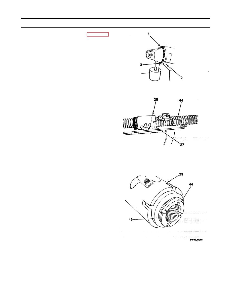
37.
Apply sealing compound (Item 6, Appendix E)
to threads in upper drain plug (1) and lower
drain plug (3).
38.
Install lower drain plug (3) into outrigger
actuator assembly (2).
39.
Install outrigger actuator assembly (2) in
horizontal jig with lower drain plug (3) down
and fill gear housing with two quarts of
hydraulic fluid. Install upper drain plug (1).
40.
Install ball screw subassembly (27) in v-blocks
on surface plate and clamp both ends to v-
blocks and table.
41.
Install C-clamp on ball nut (29) with C-clamp
handle resting on edge of surface plate to keep
ball nut from rotating on ball screw (44).
42.
Install magnetic base indicator on ball screw
(44) with stylus on end face of ball nut (,29).
NOTE
If backlash is more than 0.013 In. (0.33 mm), ball screw subassembly must be replaced.
43.
Push and pull on ball nut (29) to read magnetic
base indicator. Repeat procedure at three
equally spaced positions. Backlash should not
be more than 0.013 in. (0.33 mm).
44.
Install ball screw subassembly (27) in vertical
jig and thread new seal (49) onto ball screw
(44) with larger outside diameter surface
outward.
45.
Hold seal (49) and rotate ball nut (29) counter-
clockwise over seal until outward face of seal
is flush with bottom of slots in ball nut.
5-46
